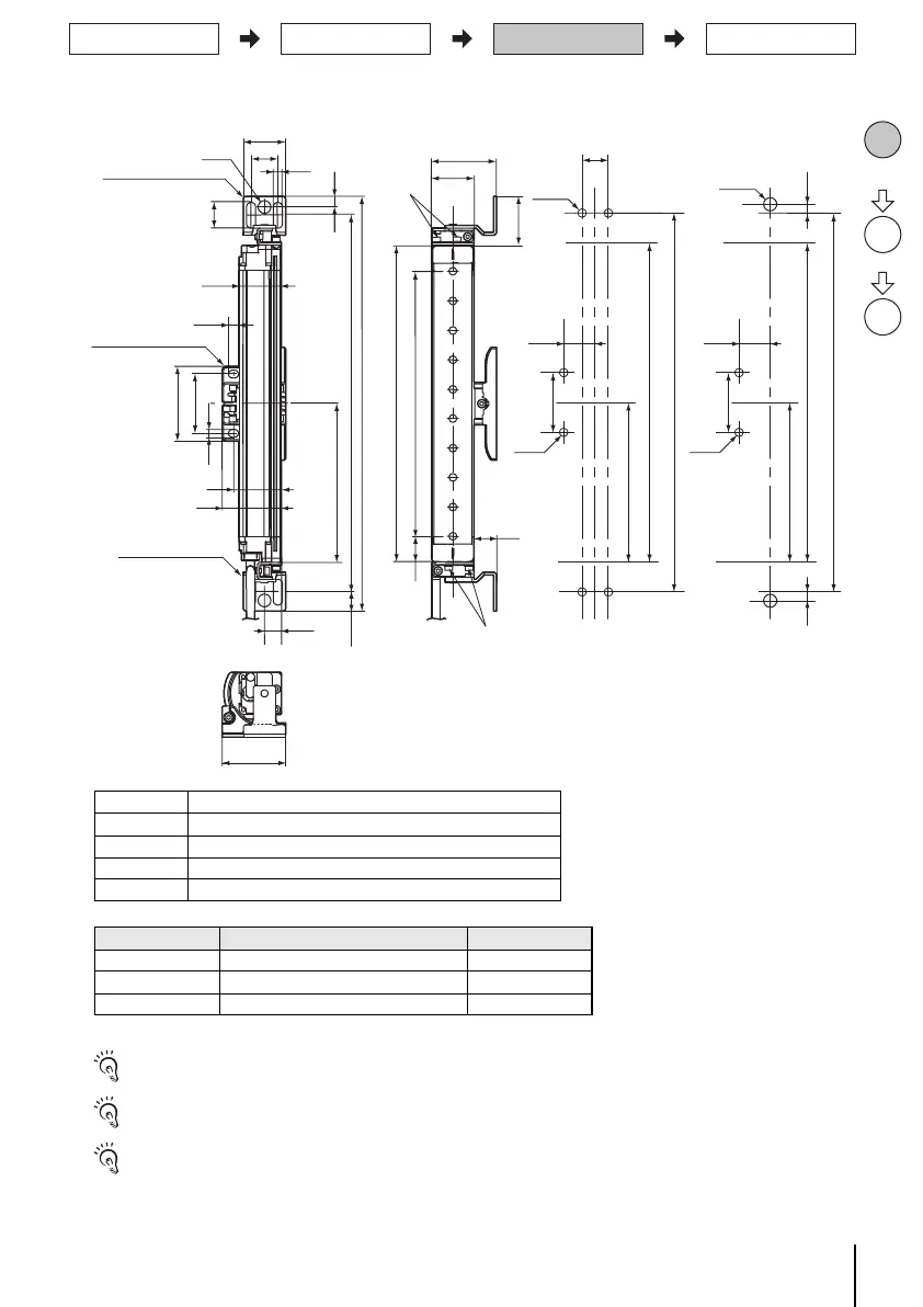
EasyManuals Logo

Omron Sti F3SJ-B P25-01TS Series User Manual

Omron Sti F3SJ-B P25-01TS Series
23 pages
To Next Page IconTo Next Page
To Previous Page IconTo Previous Page
Page #7 background imageLoading...
Page #7 background image
6
F3SJ-B-01TS
Quick Installation Manual
Dimensions (Check position)
M3 x 6 screw
M3 x 6 screw
12
34.5
Top/Bottom Bracket
(F39-LJB1)
Top/Bottom Bracket
(F39-LJB1)
Intermediate Bracket
(F39-LJB2)
E
13.4
34
42
53
42
5.5
30
7
18.3
dia.9
30
19
6.5
7.5
B
A
22.5
D
C (Protective height)
16
46
30
45
<M5 screw fixed> <M8 screw fixed>
19
B
B
E
C
C
E
42
42
5.9 5.9
22 22
4-M5
2-M8
2-M5 2-M5
[ Unit : mm ]
[Side mounting]
If the protective height exceeds 1105mm, use the intermediate brackets as many as and on the positions specified in the
dimensional drawing. Otherwise ratings/specifications cannot be satisfied.
If load is applied to the sensor unit in your environment, add intermediate bracket(s).
For mounting brackets other than top/bottom brackets (F39-LJB1) and intermediate brackets (F39-LJB2) as well as external
dimensions, refer to F3SJ-B-01TS series user's manual.
Dimensions A to E
Dimensions E
* Value E must be 700 mm or less when not using value E obtained from the calculation above.
AC+69
BC+42.2
C 4-digit number of the type name (protective height)
DC-45
E Depends on the protective height. See the table below.
Protective height Number of Intermediate Brackets Dimensions E
0185 to 1105 0 -
1185 to 1345 1 C/2 max.
1425 to 2065 2 C/3 max.
Check
position
Step1
Mount
Step2
Align
beams
Step3

Questions and Answers:

Question and Answer IconNeed help?

Do you have a question about the Omron Sti F3SJ-B P25-01TS Series and is the answer not in the manual?

Omron Sti F3SJ-B P25-01TS Series Specifications

General IconGeneral
BrandOmron
ModelSti F3SJ-B P25-01TS Series
CategorySafety Equipment
LanguageEnglish

Related product manuals