Appendix CSample Programs
116
Sample Program 5: Scaling
A/D conversion values are converted into BCD data whose full scale is set by the lower-limit value data and upper-
limit value data and retrieved as scaling data. The DM 0000 value will vary depending on the input signal range of
the input number subject to scaling.
Unit Settings
Item Setting contents Actual settings
Unit C200H-AD003 ---
Unit number #0 Unit number switch: 0
Operation mode Normal mode Back-panel DIP switch: All OFF
Input 1 used --- DM 1000 = 0001
Program Example
The following program can be executed only with the C200HS, C200HX/HG/HE CPU Units.
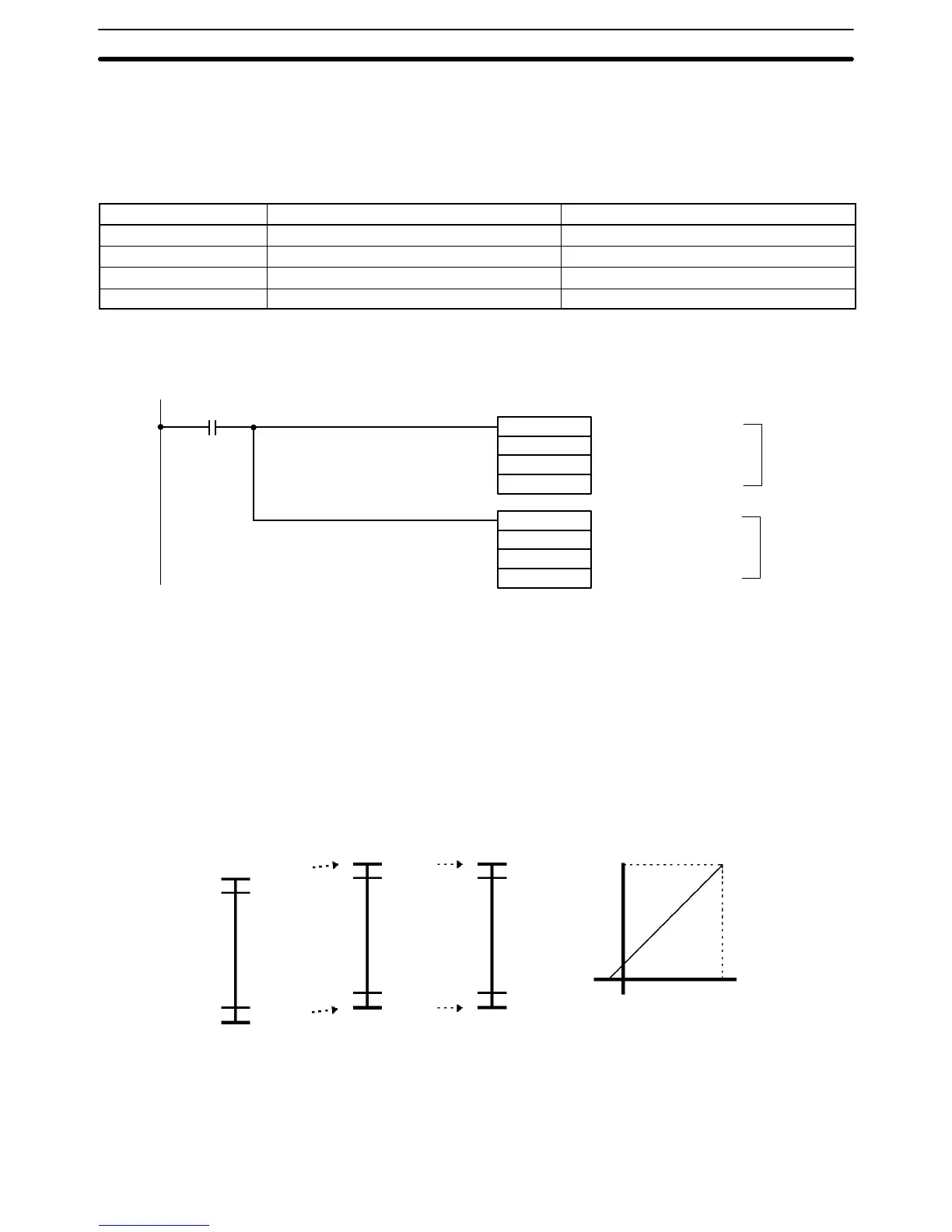
• Data Flow (Unit Number 0): Word 101 → Word 200 (scaling result)
ADB(50)
101
DM0000
DM0001
SCL(––)
DM0001
DM0002
200
(1)
(2)
Execution condition
Conversion value +
Negative number
Conversion is executed
using augmented value.
Result is output to word
200.
1, 2, 3... 1. Negative numbers cannot be used as conversion values with the SCL in-
struction, so the negative portion (0 V–5%, 1 V–5%, 4 mA–5%) is aug-
mented.
2. The lower limit (FF38) to upper limit (1068) range is scaled to a range of 0 to
4400 BCD, and output to word 200.
DM Area Setting Value for All Input Signal Ranges
Input Signal Range: 0 to 10 V / 1 to 5 V / 4 to 20 mA
The following shows a case where conversion data (full-scale) for the input signal range of 0 to 10 V is scaled to a
range of 0 to to 4400 BCD.
• Data Flow (0 to 10 V range)
+10.5 V
+10.0 V
0.0 V
–0.5 V
1068(BIN)
0FA0(BIN)
0000(BIN)
FF38(BIN)
1130(BIN)
1068(BIN)
00C8(BIN)
0000(BIN)
4400(BCD)
4200(BCD)
0200(BCD)
0000(BCD)
4400
0200
–0.5 V (FF38) 10.5 V (1068)
Word 101 value Program (1) Program (2) Final