2-4SectionIR and DM Areas
18
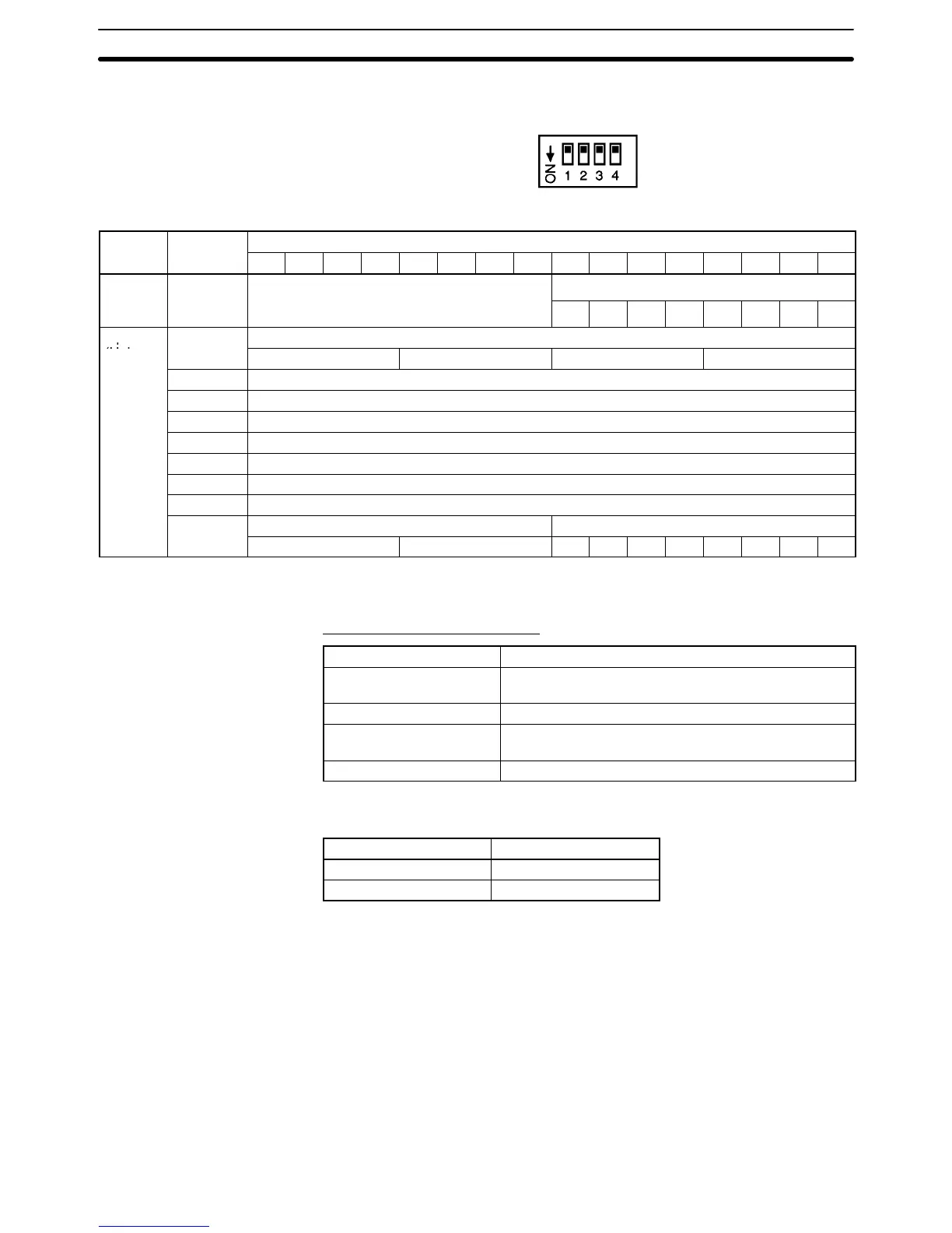
For normal mode, set the operation mode switch on the rear panel of the Unit as
shown in the following diagram.
The allocation of IR words and bits is shown in the following table.
I/O Word
Bits
15 14 13 12 11 10 9 8 7 6 5 4 3 2 1 0
Output
n+2 Input 2 conversion value
n+3 Input 3 conversion value
n+4 Input 4 conversion value
n+5 Input 5 conversion value
n+6 Input 6 conversion value
n+7 Input 7 conversion value
n+8 Input 8 conversion value
n+9
Error code Disconnection detection inputs
16
1
16
0
8 7 6 5 4 3 2 1
Note For the IR word addresses, n = 100 + 10 x unit number.
For Units #A to #F (10 to 15), n = 400 + 10 x (unit number – 10).
Set Values and Stored Values
Item Contents
Peak value function 0: Do not use.
1: Use peak value.
Conversion value 16-bit binary data
Disconnection detection 0: No disconnection
1: Disconnection
Error code Two digits, hexadecimal (00 for no error)
The disconnection detection function can be used when the input signal range is
set for 1 to 5 V (4 to 20 mA).
Input signal range Voltage/current
1 to 5 V 0.3 V max.
4 to 20 mA 1.2 mA max.
Allocation for Normal
Mode