20
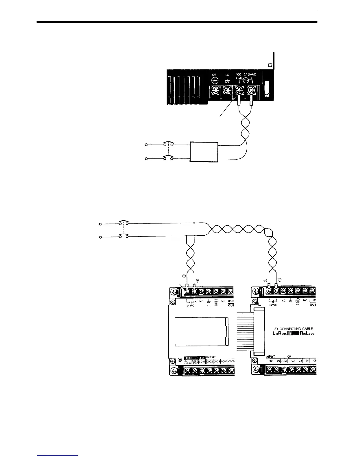
Connect an I/O Link Unit as shown in the following diagram, using M4 termi-
nal screws.
M4 screws
100 to 240 VAC
Insulating
transformer
1:1
Breaker
The following diagram illustrates the proper wiring for CPUs and Expansion
I/O Units with the suffix ”–D.” These models use a power supply of 24 VDC
with an operating voltage range of 20.6 to 26.4 VDC. Be careful to connect
the positive and negative terminals correctly. When power is turned ON, the
incoming current will be approximately 30 A.
Breaker
M3.5 screws
Ground The Line Ground (LG) terminal is a noise filter neutral terminal which does
not normally require grounding. When electrical noise is a problem, however,
this terminal should be connected to the GR terminal.
Attach an independent ground–wire with a cross–sectional area of at least 2
mm
2
(AWG 14) to the GR terminal, to avoid electrical shock. Ground resis-
Wiring CPUs and Expansion I/O Units Section 2–5