35
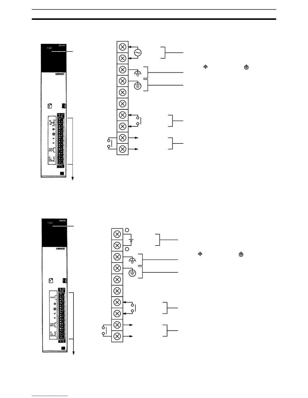
CV500-PS221/CVM1-PA208
POWER
Indicator
Lights when power
is supplied.
T
erminals for external
connections
STAR
T input
RUN output
Connect a 100 to 120-V
AC or 200 to
240-VAC power source.
Short the (LG) terminal to the (GR)
terminal to improve noise immunity and
prevent electric shock.
AC input
Ground this terminal at a resistance of
less than 100
W to prevent electric shock.
Use an independent ground not shared
with other equipment.
These terminals are short-circuit at
the factory
. Remove the sort-circuit
bracket to allow enabling and disab
-
ling of the PC with an external signal
(input: 24 VDC,10 mA). Normally
,
leave them short-circuited. These ter
-
minals are used on CPU Racks only.
These terminals are turned ON during RUN
operation.
Maximum Switching Capacity:
250 V
AC: 2 A (resistive load, cosf
= 1)
250 V
AC:
0.5 A (inductive load, cos
f
= 0.4)
24 VDC:
2 A
NC
NC
CV500-PS211
POWER Indicator
Lights when power
is supplied.
T
erminals for external
connections
STAR
T input
RUN output
Connect a 24-VDC power source.
Short the (LG) terminal to the (GR)
terminal to improve noise immunity and
prevent electric shock.
DC input
Ground this terminal at a resistance of
less than 100
W to prevent electric shock.
Use an independent ground not shared
with other equipment.
These terminals are short-circuited at
the factory
. Remove the sort-circuit
bracket to allow enabling and disab
-
ling of the PC with an external signal
(input: 24 VDC, 10 mA). Normally
,
leave them short-circuited. These ter
-
minals are used on CPU Racks only.
These terminals are turned ON during RUN
operation.
Maximum Switching Capacity:
250 V
AC: 2 A (resistive load, cosf
= 1)
250 V
AC:
0.5 A (inductive load, cos
f
= 0.4)
24 VDC:
2 A
Maximum Switching Capacity when Meeting
EC Directives (Low-voltage Directives):
24 VDC:
2 A
NC
NC
Note When complying with EC Directives (low voltage), use rein-
forced
insulation or double insulation on the DC power supply
.
Rack Components Section 2-3
 Loading...


