49
When
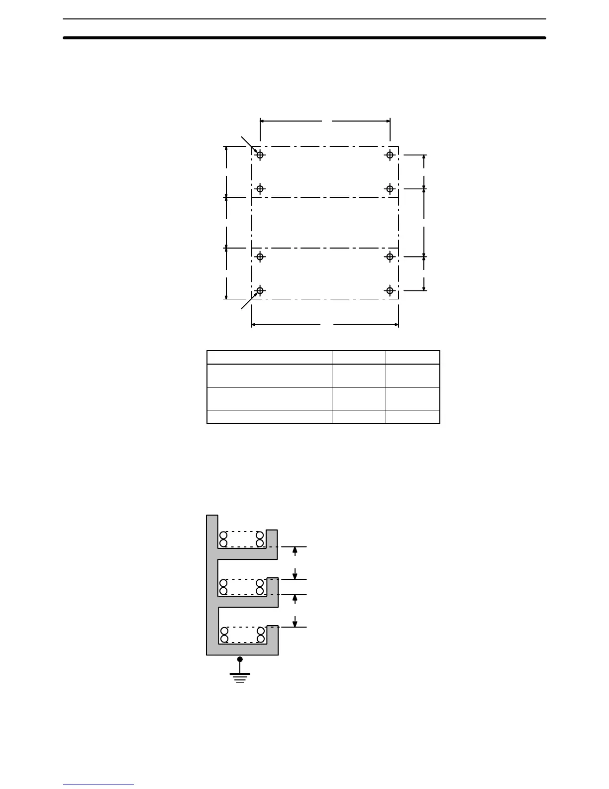
mounting the PC in a control
panel, mount the Racks to an intermediate
plate.
Holes for mounting the Racks to the intermediate plate should
be drilled at
intervals shown in the following diagram. Completely ground the intermediate
mounting plates. Use conductor-plated plates to improve noise immunity.
CPU
Backplane
CV500-BC101/051/031
CVM1-BC103/053
Expansion CPU Backplane
Expansion I/O Backplane
CV500-BI111/112/062/042
CVM1-BI114/064
Four
, M5
Four
, M5
70 to 120
L
170 to 220
W
250
250 1500.5
1500.5
Model W L0.5
CV500-BC101/BI111/112
CVM1-BC103/BI114
480 465
CV500-BC051/BI062
CVM1-BC053/BI064
306 291
CV500-BC031/BI042 236 221
3-3-1 Duct Work
If
power cables carrying more than 10 A at 400 V or 20 A at 220 V must be run
parallel to I/O wiring,
leave at least 300 mm between the power cables and the
I/O wiring, as shown in the following diagram.
Low current cables
Control cables
Power cables
300 mm min.
300 mm min.
1
2
3
Grounding at resistance
of less than 100 W
1 = I/O wiring
2 = General control wiring
3 = Power cables
Mounting Racks Section 3-3
 Loading...


