ix
About this Manual:
This manual describes the installation of the SYSMAC CV-series Programmable Controllers (CV500,
CV1000,
CV2000, and CVM1). This manual is designed to be used together with three CV
-series PC op
-
eration
manuals. The entire set of CV
-series PC manuals is listed
below
. Only the basic portions of the
catalog numbers are given; be sure you have the most recent version for your area.
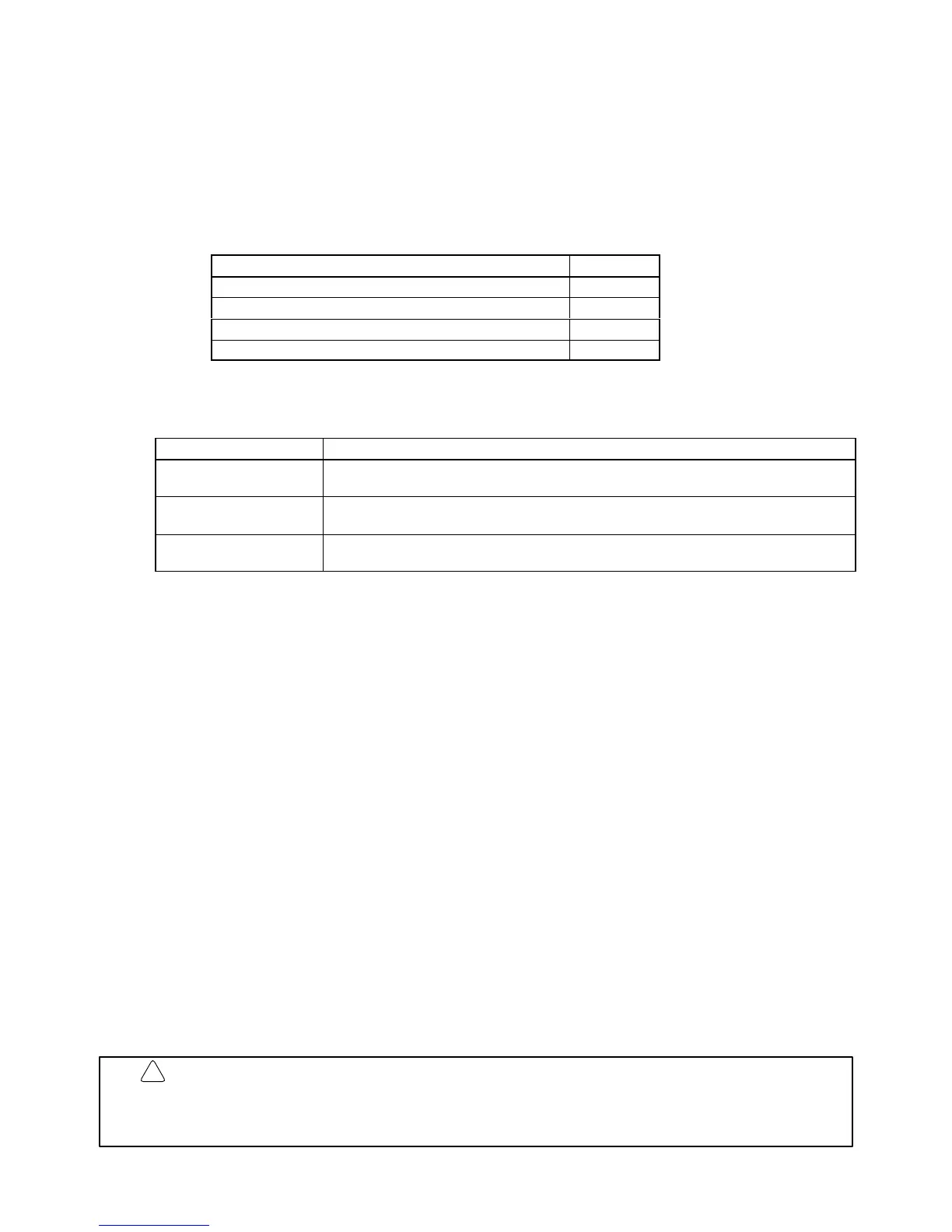
Manual Cat. No.
CV-series PC Installation Guide W195
CV-series PC Operation Manual: SFC W194
CV-series PC Operation Manual: Ladder Diagrams W202
CV-series PC Operation Manual: Host Interface W205
Programming and operating CV-series PCs are performed with the CV Support Software (CVSS), the
SYSMAC
Support Software (SSS), and the CV
-series Programming Console
for which the following man
-
uals are available.
Product Manuals
CVSS The CV Series Getting Started Guidebook (W203) and the CV Support Software
Operation Manuals: Basics (W196), Offline (W201), and Online (W200).
SSS SYSMAC Support Software Operation Manuals: Basics (W247), C-series PC Op-
erations (W248), and CVM1 Operations (W249)
CV-series Programming
Console
CVM1-PRS21-E Programming Console Operation Manual (W222)
Note The
CVSS does not support new instructions added for version-2 CVM1 PCs. The SSS does not
support SFC programming (CV500, CV1000, or CV2000).
Section 1
introduces programmable controllers in general and provides tables of the Units the can be
used
with CV
-series PCs and operation manuals available for CV
-series products. Special products used
to
create networks, enable remote I/O, or provide additional programming capabilities are also provided.
Tables
are also provided of new products included for the first
time in this version of the manual, along with
a comparison of CPU capabilities, and a list of improvements made in recent CPU versions.
Section
2
describes the overall configuration that the PC System
can take and introduces the main Units
used in the system configuration.
Section 3
provides procedures on installing and wiring.
Section 4
provides information on ongoing maintenance.
Section 5
describes general troubleshoot and provides troubleshooting flowcharts.
Appendix A
provides tables of C- and CV-series products that can be used with CV-series PCs.
Appendix
B
provides general PC specifications, dimensions, and I/O Unit specifications (including inter
-
nal circuit configurations and wiring diagrams).
WARNING Failure to read and understand the information provided in this manual may result in
personal injury or death, damage to the product, or product failure. Please read each
section
in its entirety and be sure you understand the information provided
in the section
and related sections before attempting any of the procedures or operations given.
!
 Loading...


