67
4. The
maximum switching capacity of the CV500-PS21
1 Power Supply Unit
is
2
A at 24 VDC when complying with EC Directives (low-voltage directives).
5. CV-series PCs that meet EC Directives meet the common emission stan-
dard
(EN50081-2) of the EMC Directives as individual products. When as
-
sembled into machinery, however, the noise generated by switching relay
outputs
can fail to
meet the standard. When noise is excessive, surge killers
must
be installed or other measures must be taken
outside of the PC. The
measures
required to meet the standard will vary with the load being driven,
wiring, the configuration of the machinery, etc.
The
following examples show means of reducing noise. These means
will
only
reduce the amount of noise and will not eliminate noise. They are pro
-
vided here as examples only.
Requirement
The
following conditions can be used to determine if measures to reduce noise
are necessary. Refer to the EN50081-2 Standard for details.
• If the loads of the devices into which the PC is built are switched less than 5
times a minute, then no measures need to be taken.
• If the loads of the devices into which the PC is built are switched 5 times or
more a minute, then measures need to be taken.
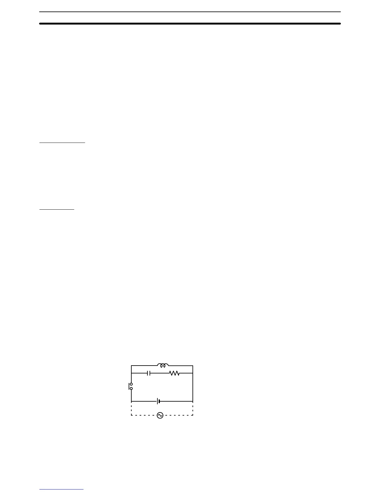
Examples
Connect
a surge suppressor or diode in parallel with the load, as shown in the
following diagrams, when switching inductive loads.
CR Method (AC or DC)
The
reset time will be increased if
the load is a relay
, solenoid, or similar device.
Connect
the CR between the load
connections for 24-V and 48-V power supply
voltages and between the contact connections for 100 to 200-V power supply
voltages.
The capacitor and resistors can be based on the following guidelines.
C: 0.5 to 1 µF for each amp of contact current
R: 0.5 to 1 Ω for each volt of contact voltage.
You
will need to adjust the above values depending on the characteristics of the
load,
relay
, etc., based on the discharge suppression of the capacitor when the
contacts
are open and the current control ef
fect of the resistor the next time the
circuit is closed.
The
dielectric strength of the capacitor generally needs
to be between 200 and
300
V
. Use an AC capacitor (without polarity) in an AC circuit.
Inductive
load
CR
Power supply
Diode Method (DC Only)
The
energy stored in the coil is impressed on the coil as a current by the action of
the
parallel diode and converted to Joule heat by the resistance
of the inductive
load.
Here, the reset time will be increased even more than for the CR method.
Inductive Load Surge
Suppressor
Compliance with EC Directives Section 3-6
 Loading...


