73
2. Detach
the
terminal block from the Output Unit, by removing the screws lo
-
cated at the top and bottom of the terminal block.
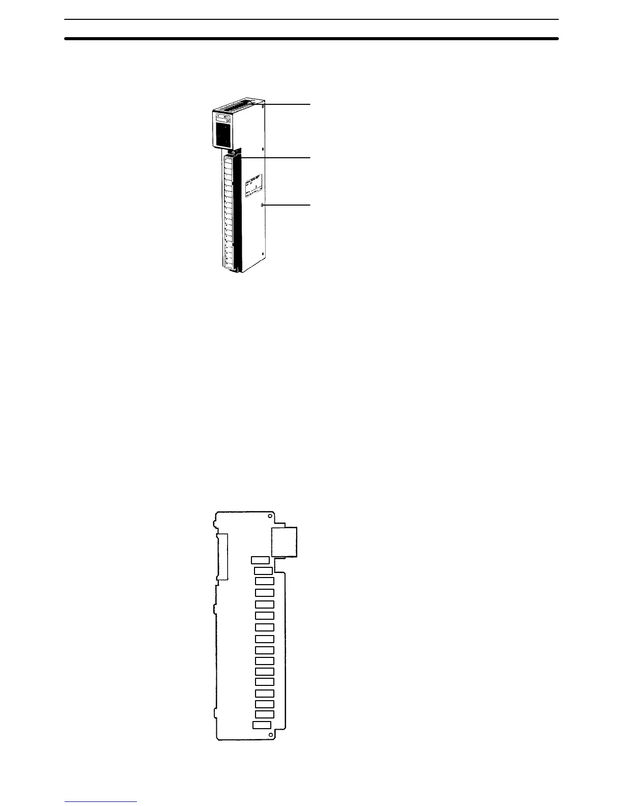
Mounting screws
Located at the top and bottom.
Terminal block mounting screws
Located at the top and bottom of the
terminal block.
Cover mounting screws (8)
3. Remove
the screws that mount the Output Unit to the Backplane. Pulling the
Unit toward you, remove the Output Unit from the Backplane.
4. There are eight screws on each side of the Output Unit. Remove these
screws to detach the case from the cover.
5. Pull out the printed circuit board.
6. Use the Relay Puller to pull out the Relay. Insert a new Relay.
7. Reassemble the Unit.
Note To
remove the
relay
, use the P6B-Y1 Relay Puller
. Be sure to insert the relay in
the
socket in the correct direction. The relay cannot be inserted in the wrong di
-
rection and if excessive force is applied to the relay, the pins of the relay may
bend. The locations of relays on the PC boards are illustrated in the following
figures.
3G2A5-OC221/223
0
1
2
3
4
5
6
7
8
9
10
11
12
13
14
15
Terminal block
Connector
Indicators
Output Unit Relays Section 4-4
 Loading...


