EasyManua.ls Logo

Omron SYSMAC NX-CIF Series User Manual

Omron SYSMAC NX-CIF Series
232 pages
To Next Page IconTo Next Page
To Previous Page IconTo Previous Page
Page #130 background image
7 Serial Communications
7 - 26
NX-series Communications Interface Units User’s Manual (W540)
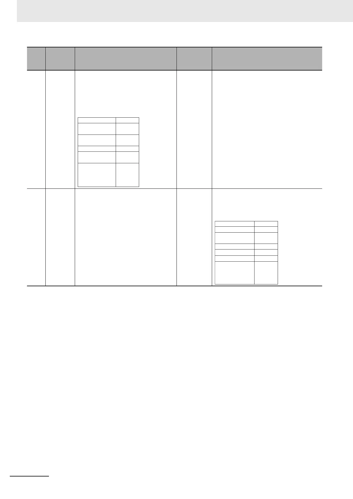
7 Checking
response
reception
• The communications master outputs
th
e following output notification data to
notify the CIF Unit that the response
was received.
• When the port is restarted, the value of
t
he Output SID is initialized to 00 hex.
ï‚®
• The CIF Unit receives the output notifica-
tion data given on the left.
• The CIF Unit knows that the response was
norma
lly received by the CPU Unit or com-
munications master because the Input SID
Re
sp
onse in the output notification data is
01 hex.
8 Response
to initia
l-
ized
Out-
put SID
• The communications master receives
th
e input notification data given on the
right.
• The communications master knows
th
at initialized Output SID was nor-
mally received by the CIF Unit because
th
e Outpu
t SID Response in the input
notification data is 00 hex.

The CIF Unit inputs the following input notifi-
cation data to tell the CPU Unit or communi-
cations master that the ini
tialized Output SID
was received normally.
*1. : Output notification data is output from the CPU Unit or communications master to the CIF Unit.
: Input notification data is input from the CIF Unit to the CPU Unit or communications master.
Step Process
CPU Unit or communications master
processing
Communi-
cations
direction
*1
CIF Unit processing
Initialization
Set the Input
SID.
00 hex
01 hex
0000 hex
0000 hex
0000 hex
00 hex,
00 hex,
00 hex,
00 hex
Output SID
Input SID
Response
Output Data
Type
Output Sub Info
Output Data
Length
Output Data 01
0010 hex
05 hex
00 hex
2000 hex
0000 hex
0000 hex
00 hex,
00 hex,
00 hex,
00 hex
Set the Output
SID.
Input Data 01
Port Status
Input SID
Output SID
Response
Input Data Type
Input Sub Info
Input Data Length

Table of Contents

Question and Answer IconNeed help?

Do you have a question about the Omron SYSMAC NX-CIF Series and is the answer not in the manual?

Omron SYSMAC NX-CIF Series Specifications

General IconGeneral
BrandOmron
ModelSYSMAC NX-CIF Series
CategoryRecording Equipment
LanguageEnglish

Summary

Introduction

Intended Audience

Describes the target audience for the manual, including engineers and personnel involved in FA systems.

Applicable Products

Lists the products covered by this manual, specifically NX-series Communications Interface Units.

Manual Structure

Page Structure and Icons

Details the standard page layout, headings, page tabs, and icons used in the manual.

Special Information

Precautions for Safe Use

Provides guidelines on actions to ensure safe usage of the product.

Precautions for Correct Use

Provides guidelines on actions to ensure proper operation and performance of the product.

Additional Information

Offers extra information to enhance understanding or ease operation.

Version Information

Details differences in specifications and functionality based on unit and software versions.

Precautions on Terminology

Terms and Conditions Agreement

Warranty, Limitations of Liability

Outlines Omron's product warranties and limitations on liability.

Application Considerations

Suitability of Use

Addresses the buyer's responsibility for determining product suitability for their specific application.

Programmable Products

States Omron's non-responsibility for user programming of programmable products.

Disclaimers

Performance Data

Explains that performance data is a guide and not a warranty, requiring user correlation.

Change in Specifications

Informs that product specifications and accessories may change without notice.

Errors and Omissions

States that no responsibility is assumed for clerical, typographical, or proofreading errors.

Safety Precautions

Definition of Precautionary Information

Explains the notation used for warnings and cautions in the manual.

Symbols

Defines the meaning of various symbols used to indicate prohibited actions or precautions.

During Power Supply

Details precautions related to electrical shock and injury when handling units with power applied.

Fail-safe Measures

Emphasizes the need for external safety measures to ensure system safety during abnormalities.

Voltage and Current Inputs

Advises ensuring input voltages and currents stay within specified ranges to prevent accidents.

Transferring

Stresses confirming safety before transferring configuration or data to prevent unexpected operations.

Online Editing

Warns about potential timing deviations and I/O refresh issues during online editing.

Cautions

Wiring

Provides precautions for safe wiring practices, including grounding and cable management.

Precautions for Safe Use

Transporting

Advises using original packaging and avoiding excessive vibration or shock during transportation.

Mounting

Details precautions for mounting terminal blocks and connectors, ensuring locking devices are secured.

Installation

Covers power-off requirements before installation, removing units, and avoiding labels on units or the NX bus connector.

Wiring

Emphasizes checking wiring and settings before power-on, using correct parts, and following cable precautions.

Power Supply Design

Covers using appropriate I/O power supply ranges, voltages, and protecting against overcurrents.

Turning ON the Power Supply

Advises confirming the system's state before powering on the unit.

Actual Operation

Details pre-operation checks, fail-soft operation considerations, and system impact verification.

Turning OFF the Power Supply

Outlines precautions for turning off power, especially during data transfers or hardware manipulation.

Operation

Emphasizes confirming system impact before operations like mode changes or value adjustments.

General Communications

Advises adhering to specified communication distance and unit count limits.

Disposal

Mentions disposing of the product according to local ordinances.

Using Communications Interface Units

Provides a specific precaution regarding polarity when connecting RS-422A/485 cables.

Precautions for Correct Use

Storage, Mounting, and Wiring

Covers correct storage, mounting, and wiring practices to prevent malfunctions or damage.

Transferring Data

Advises confirming system impact before transferring communication settings.

Actual Operation

Mentions confirming safety before changing event levels and not exceeding power supply capacity.

Turning OFF the Power Supply

Warns against turning off power during data transfer or parameter writing.

General Communications

Refers to other manuals for communication precautions with connected coupler units.

Unit Replacement

Provides a tip on how to remove multiple units together for easier detachment.

Regulations and Standards

Conformance to EU Directives

Details EU Directives compliance, including EMC and Low Voltage Directives, and required installation precautions.

Conformance to UL and CSA Standards

Mentions compliance with UL and CSA standards and refers to instruction sheets for conditions.

Conformance to Shipbuilding Standards

Covers compliance with shipbuilding standards, advising consultation with OMRON representatives.

Conformance to KC Certification

Addresses KC certification requirements and precautions for use in Korea.

Software Licenses and Copyrights

Provides information on third-party software licenses and copyright information.

Unit Versions

Unit Versions

Explains the concept of unit versions and how to identify them on the product.

Notation of Unit Versions on Products

Illustrates where to find unit model and version information directly on the product.

Confirming Unit Versions with the Support Software

Guides on how to confirm unit versions using the Support Software.

Unit Versions and Support Software Versions

Explains the dependency of supported functions on unit and support software versions.

Related Manuals

Terminology

Revision History

Sections in this Manual

1 Features and System Configuration

1-1 Features of Communications Interface Units

Details the features of CIF Units as Sysmac devices, NX Units, and serial communication devices.

1-2 System Configuration

Describes how CIF Units connect to NX-series CPU Units and Communications Coupler Units.

1-3 Unit Models, Functions, and Support Software

Lists available CIF Unit models, their functions, and required support software.

1-4 Serial Communications Instructions for the CIF Units

Explains the serial communications instructions available for programming CIF Units.

1-2-1 System Configuration with CIF Unit Connected to CPU Unit

1-2-2 System Configuration of Slave Terminals

1-3-1 Unit Model Numbers

1-3-2 Functions

1-3-3 Support Software

1-4-1 Serial Communications Instructions for CIF Units

1-4-2 Conditions for Using Serial Communications Instructions for CIF Units

2 Specifications and Application Procedures

2-1 Specifications

Provides general specifications for the CIF Units, including enclosure and grounding.

2-2 Application Procedures

Outlines the procedures for applying CIF Units, from creating settings to checking operation.

2-1-1 General Specifications

2-1-2 Specifications of Individual Units

3 Part Names and Functions

3-1 Part Names

Identifies the parts of the NX-CIF101 and NX-CIF105 units.

3-2 Indicators

Describes the indicators on the CIF Units that show operating status and signal I/O.

3-1-1 NX-CIF101 and NX-CIF105

3-1-2 NX-CIF210

3-2-1 TS Indicator

3-2-2 Send/Receive Indicators

3-2-3 Appearance Change of the Indicators

4 Installation and Wiring

4-1 Installing NX Units

Refers to other manuals for information on installing NX Units, including CIF Units.

4-2 Connecting the Power Supply and Ground Wires

Guides on wiring power supply and ground for CIF Units, with additional information on I/O power and FG terminals.

4-3 Wiring the Terminals

Details how to wire terminals on CIF Units, emphasizing screw tightening and safe practices.

4-4 Wiring Communications

Explains how to wire CIF Units for communications with external serial devices.

4-3-1 Wiring the Screwless Clamping Terminal Blocks

Connecting/Removing Wires

Explains how to connect and remove wires from terminal blocks, including required tools.

Preventing Incorrect Attachment of Terminal Blocks

Describes how to use coding pins to prevent incorrect attachment of terminal blocks to units.

4-3-2 Wiring the D-Sub Connector

4-4-1 Terminal Arrangement

NX-CIF105 Terminal Arrangement

Shows the terminal arrangement for the NX-CIF105 unit.

Arrangement of D-sub Connector Pins on NX-CIF210

Lists the D-sub connector pin arrangements for the NX-CIF210 unit.

4-4-2 Connecting to Serial Communications Devices

4-4-3 Examples of Recommended RS-232C and RS-422A/485 Wiring

5 I/O Data Specifications

5-1 I/O Data Specifications for NX-CIF101 and NX-CIF105

Details the data that can be set for I/O allocations, corresponding to NX objects for NX-CIF101/105.

5-2 I/O Data Specifications for NX-CIF210

Details the data that can be set for I/O allocations, corresponding to NX objects for NX-CIF210.

6 Unit Settings

6-1 Unit Operation Settings

Explains the operation settings for a CIF Unit, including communications specifications, buffering, and event levels.

6-2 Unit Operation Setting Procedure

Details the procedure for setting Unit operations using Support Software like Sysmac Studio.

6-3 Setting the Divided Data Size

Describes how to set the divided data size to optimize communications performance.

6-1-1 Communications Specifications

6-1-2 Transmission Buffering

6-1-3 Event Levels

7 Serial Communications

7-1 No-protocol Communications

Describes no-protocol communications and its use for sending/receiving data from serial devices.

7-2 How Data Is Sent and Received

Explains how send and receive buffers are used in CIF Units for data transfer.

7-3 Data Used by the Serial Communications Protocol

Details the data used in serial communications protocol processing between master and CIF Unit.

7-4 Examples of Communications between CPU Unit or Communications Master and CIF Unit

Provides examples of communications between CPU units/masters and CIF units.

7-5 User Programming to Send Data

Describes the processing for sending data within user programs.

7-6 User Programming to Receive Data

Outlines the processing for receiving data within user programs.

7-7 User Programming to Restart a Port

Explains the processing for restarting a port in user programs.

7-8 Communications Performance

Describes how to calculate communications performance and adjust data sizes for optimization.

7-2-1 How Data Is Sent

7-2-2 How Data Is Received

7-3-1 Input Notification Data and Output Notification Data

7-3-2 SIDs and SID Responses

7-3-3 Input Data Type and Output Data Type

7-3-4 Send Completed Toggle Bit

7-4-1 Example of Sending Data

7-4-2 Example of Receiving Data

7-4-3 Simultaneously Sending and Receiving Data

7-4-4 Example for a Parity Error during Data Reception

7-4-5 Example of Control Command Execution

7-5 User Programming to Send Data

7-5-1 Creating and Outputting Output Notification Data

Describes creating and outputting notification data for sending data, handling data division.

7-5-2 Checking Input Notification Data

Explains how user programs should check input notification data to confirm correct reception.

7-5-3 Processing Send Data

Details necessary processing on send data, such as adding start codes, end codes, or CRC.

7-6 User Programming to Receive Data

7-6-1 Checking Input Notification Data

Outlines checking input notification data for storing received data and detecting errors.

7-6-2 Creating and Outputting Output Notification Data

Explains creating and outputting notification data to inform the CIF Unit about normal reception.

7-6-3 Determining Conditions to Start Reception and Conditions for the Completion of the Reception

Covers setting reception start and completion conditions, including checking for end detection.

7-6-4 Precautions for Writing User Programming to Receive Data

Provides precautions for writing user programs to receive data, especially regarding buffer sizes and errors.

7-8-1 Calculating the Communications Performance

7-8-2 Adjusting Divided Data Sizes to Improve Communications Performance

7-8-3 Processing When the Send Buffer or Receive Buffer Becomes Full

8 Serial Line Monitor

8-1 How the Serial Line Monitor Works

Explains the serial line monitor's function to log, display, and save sent/received data.

8-2 Support Software Operations

Details operations for using the serial line monitoring feature within the Support Software.

8-1-1 Monitor Data Contents

8-1-2 CIF Serial Line Monitor Tab Page

8-1-3 Processing When a Buffer Becomes Full

8-1-4 Importing and Exporting Monitor Data

8-1-5 Searching for Text Strings in Monitor Data

8-1-6 Creating CSV Files of Monitor Data

8-1-7 Processing for Multiple Units and Ports

8-2-1 Displaying the CIF Serial Line Monitor Tab Page

8-2-2 Starting and Stopping Monitoring and Displaying Monitor Data

9 Troubleshooting

9-1 How to Check for Errors

Outlines methods for checking errors, including using indicators and support software.

9-2 Checking for Errors with the Indicators

Explains how to interpret CIF Unit indicators to identify and troubleshoot errors.

9-3 Checking for Errors and Troubleshooting on the Support Software

Details how to check for and troubleshoot errors using support software like Sysmac Studio.

9-4 Resetting Errors

Refers to other manuals for information on resetting errors.

9-5 Troubleshooting Flowchart

Refers to other manuals for standard troubleshooting processes.

9-3-1 Checking for Errors from the Sysmac Studio

9-3-2 Checking for Errors from Support Software Other Than the Sysmac Studio

9-3-3 Event Codes for Errors and Troubleshooting Procedures

Controller Error Descriptions

Describes the items used to detail individual errors, including event name, code, meaning, source, and recovery.

10 Maintenance and Inspections

10-1 Cleaning and Inspections

Describes daily maintenance and cleaning/inspection methods for CIF Units.

10-2 Maintenance Procedures

Refers to other manuals for data backup and replacement procedures for CIF Units.

10-1-1 Cleaning

10-1-2 Periodic Inspection

Appendices

A-1 Dimensions

Provides dimensional drawings for NX-CIF101/105 and NX-CIF210 units.

A-2 Changing NX Objects from a User Program

Explains how to change NX objects of the CIF Unit using user programs and specific instructions.

A-3 List of NX Objects

Describes NX objects of CIF Units, their access methods, and object descriptions format.

A-4 Programming Samples

Offers ST language programming samples for using CIF Units with serial devices.

A-5 Version Information with CPU Units

Provides version-related information for connecting Units to a CPU Unit.

A-6 Version Information with Communications Coupler Units

Details version information for connecting Units to Communications Coupler Units.

A-1-1 NX-CIF101 and NX-CIF105

A-1-2 NX-CIF210

A-2-1 NX Objects That You Can Change

A-2-2 Procedure to Change NX Objects

A-3-1 Format of NX Object Descriptions

A-3-2 NX Objects for the NX-CIF101 and NX-CIF105

A-3-3 NX Objects for the NX-CIF210

A-4-1 Items Common to all Programming Samples

A-4-2 Programming Sample 1: Restarting CIF Unit Ports

A-4-3 Programming Sample 2: Sending Data

A-4-4 Programming Sample 3: Receiving Data

A-5-1 Relationship between Unit Versions of Units

A-6-1 Connection to an EtherCAT Coupler Unit

A-6-2 Connection to an EtherNet/IP Coupler Unit

Related product manuals