12
SECTION 1
What is a CIDRW System?
CIDRW System
User’s Manual
SECTION 1
Product Outline
What is a CIDRW System?
The CIDRW system writes data to, and reads data from, the carrier IDs (ID Tags) mounted on the carriers
(FOUP) in semiconductor manufacturing processes without contacting these ID Tags. CIDRW is the
abbreviation of "Carrier ID Reader/Writer" and this abbreviation is used throughout this manual.
Reading and writing information such as models, process instructions, lots, and inspection results to and from
ID Tags makes it possible to manage work instruction information from a host device.
Example: Management of information in semiconductor and wafer manufacturing processes
ID Tag
(holder is separate)
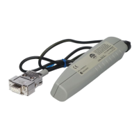
CIDRW Head
Reading and writing
information
• Model information
• Process instruction
information
• Completion
information
• Lot information
• Inspection results
Etc.
Host
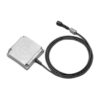
Amplifier Unit
CIDRW Controller