5
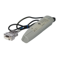
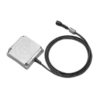
CIDRW System
User’s Manual
INTRODUCTION
Notice
INTRODUCTION
Notice
The CIDRW System is highly reliable and resistant to most environmental factors. The following guidelines, however, must
be followed to ensure reliability and optimum use of the CIDRW System.
Installation Site
Install the product at a location where:
• It is not exposed to direct sunlight.
• It is not exposed to corrosive gases, dust, metal chips, or salt.
• The working temperature is within the range stipulated in the specifications.
• There are no sudden variations in temperature (no condensation).
• The relative humidity is within the range stipulated in the specifications.
• No vibration or shock exceeding the values stipulated in the specifications is transmitted directly to
the body of the product.
• It is not subject to splashing water, oil, or chemical substances.
Mounting
• This product communicates with ID Tags using the 134 kHz frequency band. Note that some trans-
ceivers, motors, monitoring equipment, and power supplies (power supply ICs) generate electrical
waves (noise) that interfere with communications with ID Tags. If you are using the product in the
vicinity of any of these devices, check the effect on communications in advance.
• In order to minimize the effects of noise, ground nearby metal bodies with a grounding resistance not
exceeding 100 ohms.
• When mounting Amplifier Units, tighten the screws with a torque no greater than 1.2 N·m.
• When mounting CIDRW Heads, tighten the screws with a torque no greater than 0.6 N·m.
• When multiple CIDRW Heads are mounted next to each other, communications performance could
be impaired by mutual interference. Note the information in this manual on mutual interference when
installing multiple heads.
Refer to page 105.