Install an approved flexible non-metallic (non-
conductive) and non-organic fuel line between theveh-
icle fuel system and the generator set to absorb vibra-
tion. Onan recommends using a seamless steel tubing
and flared connection
for
long runs between the fuel
tank and the flexible connector to the generator set.
aldotIurV~~)
Mu3
confonn
to
ASME
or dol and
CTC
slandards. (Working pressure
A
manual shut-0% valve MUST be mounted on the pro-
pane fuel supply tank. This supply tank valve
MUST
be
fully open when operating the generator set
to
ensure
the excess flow valve
will
close with a severed (broken)
propane fuel line.
Must
Close
with
Completeline
Breakage. Consult National
LP
Gas
Associalion Publication
113-78
For Limitations.
VblQZ
.-A
hydrostatic pressure relief valve MUST be installed
between the propane fuel supply tank manual shut-off
valve and the propane fuel solenoid valve and filter
assembly
.
This relief valve protects the propane fuel line from
pressure buildup if both the supply tank manual shut-off
valve and the fuel solenoid valve are closed at the same
time.
Testing
Fuel
System
for
Leaks
The completed propane fuel system installation MUST
be checked and tested for leaks before the generator set
is operated. The fuel solenoid MUST be energized from
a separate
12
volt
DC
source before testing the fue
system for leaks. The test
MUST
conform to procedure:
listed in
NFPA-58,
Paragraph
318,
or
UL recommended
test procedure as follows:
After assembly and prior
lo
initial operation,
all
iuel
system
connec-
tions, hose, valves, regulators,and fittings must
be
testedand proven
free
of
any leaks using a soap and water
or
equivalent solution while
the system
is
under
a
gas
or
air
pressure
of
not
less
than
90
pounds
per square inch
(620
kPa).
Other approved methods of detecting leaks
may
be
used if appropriate. Test shall
NOT
be made with a
flame.
.
..
Liquid
LPG
fuel presents
fhe
hazard
EiSSiEI
'
of
explosion
or
fire which can result
in severe personal injury
or
deafh.
Do
not smoke
or
allow any ignition sources in the installation area.
CARBURETOR
*l/enluri
lype
with
bolh
a "Main" and
!et adjustments.
when
carburetor provides suclion
Io
fuel
outlet.
"
C.
I
'Idle-
.w
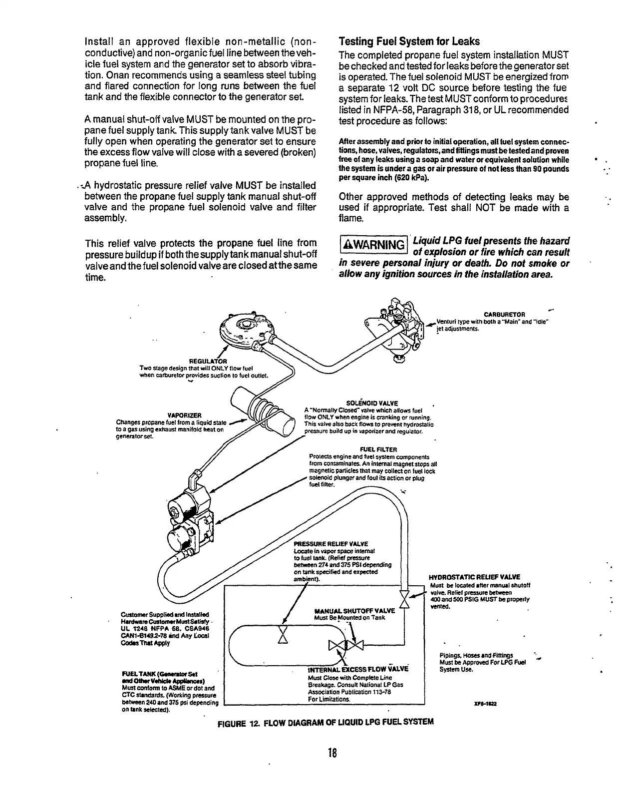
FIGURE
12
FLOW
DIAGRAM
OF
UQUID
LPG
FUEL
SYSTEM
18
Redistribution or publication of this document,
by any means, is strictly prohibited.