Keep fuel lines awayfrom hot
engine
or exhaust areas.
This
reduces chance
of
vaporlock. Install lines
so
that
they are accessible and protected from damage. Use
metal straps without sharp edges
to
secure them.
No
&ad
Half
Load
0.5
gal/hr
0.8
gal/hr
(1.9
I/hr)
(3.0
Vhr)
Flexible
line
must
be
long
enough to allow for set
movement
in
order to prevent
binding,
stretching
or
breaking.
PROPANE
(LPG)
FUEL
SYSTEM
(60
Hz
Only)
+-
Fuel
System
Provisions
'
.-
.
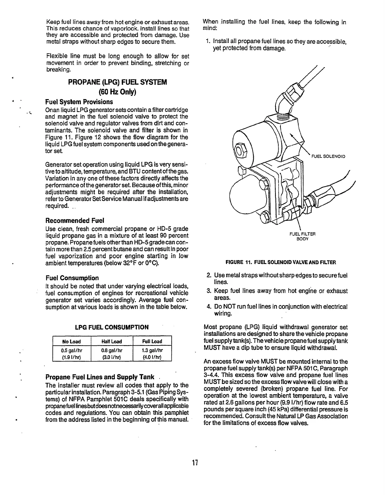
Onan
liquid
LPG
generator sets contain afiltercartridge
and magnet
in
the fuel solenoid valve to protect
the
solenoid valve and regulator valves from
dirt
and con-
taminants. The solenoid valve and
filter
is
shown
in
Figure
11.
Figure
12
shows the flow
diagram
for
the
liquid
LPG
fuel system components
used
on thegenera-
tor
set
Full
Load
1.3 gal/hr
(4.0
I/hr)
Generator set operation
using
liquid
LPG
is
very
sensi-
tive to altitude, temperature, and
BTU
content of
the
gas.
Variation
in
any one of these factors directly affects the
performance of the generator
set.
Because of
this,
minor
adjustments
might
be
required
after the installation,
refer to Generator Set Service
Manual
if
adjustmentsare
required.
.,
Recommended
Fuel
Use clean, fresh commercial propane or
HD-5
grade
liquid
propane gas
in
a
mixture
of
at
least
90
percent
propane. Propane
fuels
otherthan
HD-5
gradecan con-
tain more than
2.5
percent butane and can
result
in
poor
fuel vaporization
and
poor
engine
starting
in
low
ambient temperatures (below 32°F or
OOC).
Fuel Consumption
It
should
be
noted that under varying electrical loads,
fuel consumption of engines for recreational vehicle
generator set varies accordingly. Average fuel con-
sumption
at
various loads
is
shown
in
the table below.
LPG
FUEL
CONSUMPTION
Propane Fuel
Lines
and
Supply
Tank
.
The installer
must
review
all
codes that apply to the
particular installation. Paragraph
3-5.1
(Gas
Piping
Sys-
tems)
of
NFPA
Pamphlet
501C
deals specifically
with
propane fuel
linesbutdoesnotnecessady
coverall applicable
codes and regulations. You
can
obtain this
pamphlet
from
the
address
listed
in
the beginning of
this
manual.
When
installing
the fuel
lines,
keep the following
in
mind:
1.
Install all propane fuel
lines
so
they are accessible,
yet
protected
from
damage.
2.
3.
4.
FUEL
FILTER
BODY
FIGURE
11.
FUEL
SOLENOlO
VALVE
AND
FILTER
Use
metal
straps
withoutsharpedges to securefuel
lines.
Keep
fuel
lines
away from hot engine or exhaust
areas.
Do
NOT
run
fuel
lines
in
conjunction
with
electrical
wiring.
Most propane
(LPG)
liquid
withdrawal generator set
installations are designed to share the vehicle propane
fuel
supplytank(s).
The
vehicle
propane fuel
supply
tank
MUST
have a dip tube to
ensure
liquid
withdrawal.
An
excess
flow
valve
MUST
be
mounted internal
to
the
propane
fuel
supplytank(s)
per
NFPA
501
C,
Paragraph
3-4.4.
This
excess
flow
valve
and propane fuel lines
MUST be sized
so
the
excess
flow
valve
will
close
with
a
completely
severed
(broken) propane fuel line. For
operation at the lowest ambient temperature, a valve
rated at
2.6
gallons per hour
(9.9
Vhr)
flow rate and
6.5
pounds
per
square
inch
(45
kPa) differential
pressure
is
recommended. Consult the
Natural
LP Gas Association
for
the
limitations of excess
flow
valves.
17
Redistribution or publication of this document,
by any means, is strictly prohibited.