DC
WIRING
Remote
Switch
Wiring
The standard remote control includes a start-stop
switch and indicator lamp. The deluxe control contains
these items plus
a
running time meter and a battery
condition meter. Install
as
follows:
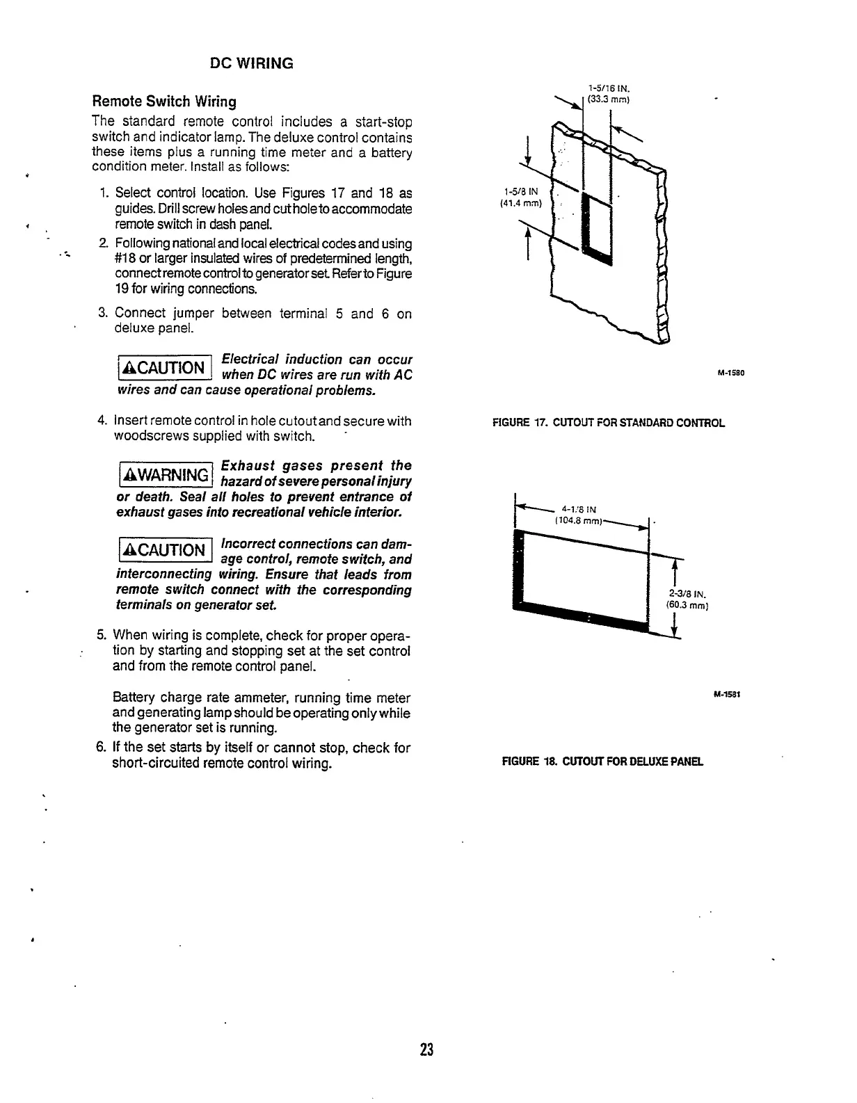
1.
Select control location. Use Figures
17
and
18
as
guides. Drill screw holes and cut hole to accommodate
remote switch in dash panel.
2.
Following national and local electrical codesand using
#18
or
larger insulated wires
of
predetermined length,
connect remote control
to
generator set
Referto
Figure
19
for
wiring connections.
3.
Connect jumper betwezn terminal
5
and
6
on
deluxe panel.
+*
..
flectrical induction can occur
'v!
when
DC
wires
are
run with
AC
wires and can cause operational problems.
4.
insert remote control in hole cutoutand secure with
woodscrews supplied with switch.
.
Exhaust gases present the
1-1
hazard
of
severe personalinjury
or death. Seal
all
holes to prevent entrance
of
exhaust gases in20 recreational vehicle interior.
-1
Incorrect connections can
darn-
age control, remote switch, and
interconnecting wiring. Ensure that
leads
from
remote switch connect with the corresponding
terminals on generator set.
5.
When wiring is complete, check
for
proper opera-
tion by starting and stopping set at the set control
and
from
the remote control panel.
Battery charge rate ammeter, running time meter
and generating lamp should be operating only while
the generator set is running.
6.
If
the set starts
by
itself
or
cannot stop, check
for
short-circuited remote control wiring.
1-5/16
IN.
-Y
(33.3;1n)
M-1580
FiGURE
17.
CUTOUT
FOR
STANDARD
CONTROL
4-1.'81N
M-1581
FIGURE
18.
CUTOUT
FOR
DELUXE
PANEL
23
Redistribution or publication of this document,
by any means, is strictly prohibited.