GENERATING LAMP
(GLOWS WHEN
SET
IS
RUNNING)
SETTERMINAL
1
2
3
6
-I
REMOTE
SWITCH WIRE COLOR
TERMINAL FUNCTION CODE
1
GROUND BLACK
2
STOP
BROWN
3
START YELLOW
LAMP
AND
RUNNING
6
TIME
MnER
RED
BATlERY
CHARGE
RATE
AMMETER
-
DELUXE PANEL
NOTE: USE
ia
GAUGE
OR
LARGER WIRE
FOR
INSTALLING THE
REMOTE START SWITCH.
BACK SIDE
OF
REMOTE REMOTE CONTROL
R
BATI'ERY
CHARGE CONNECTOR SWITCH
METER
RATE
AMMETER
c-
STANDARD PANEL
GENERATING LAMP
IS
RUNNING1
[GLOWS WHEN SET
ES-1530
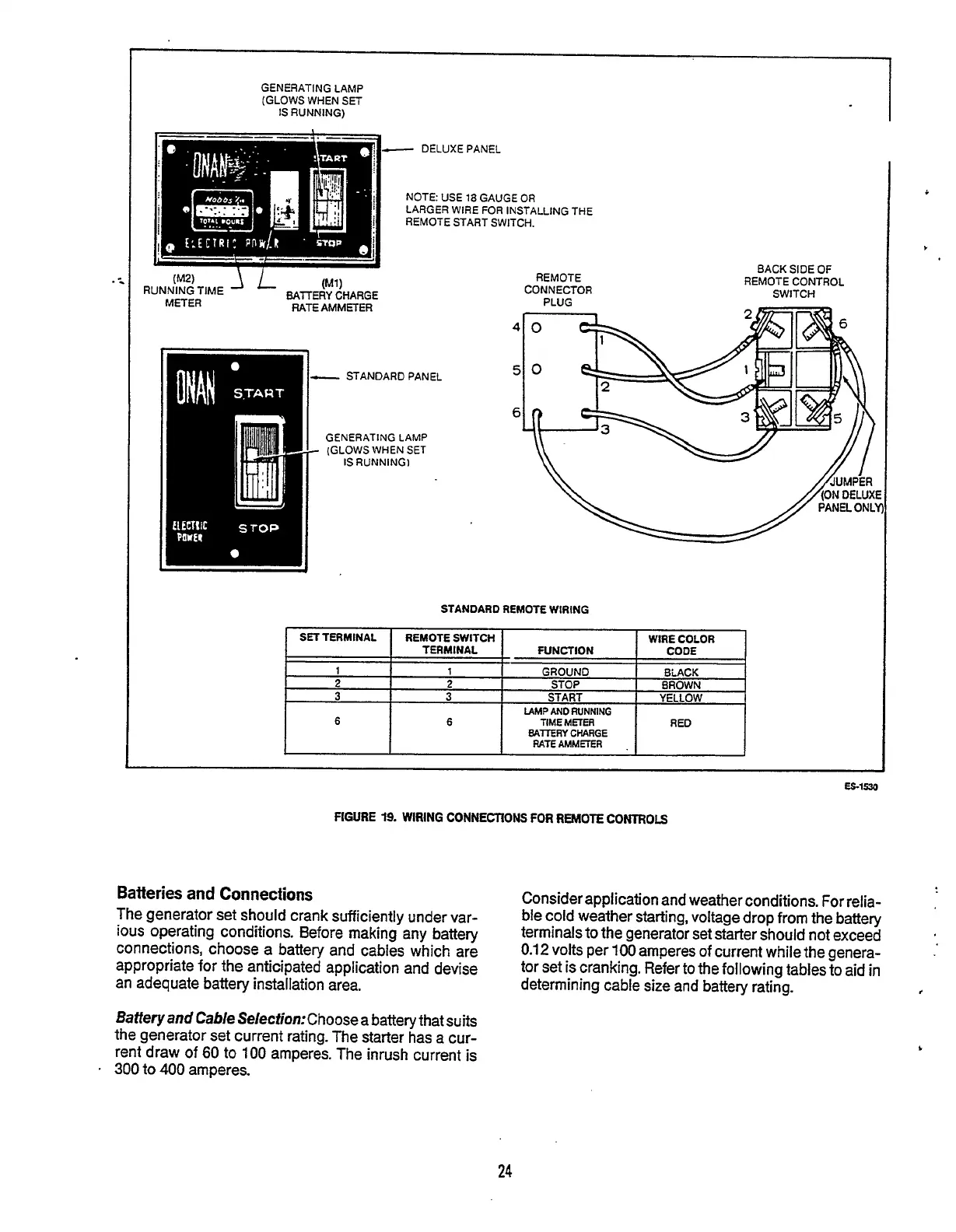
FIGURE
19.
WIRING
CONNECTIONS
FOR
REMOTE
CONTROLS
Batteries
and
Connections
The generator set should crank sufficiently under var-
ious operating conditions. Before making any battery
connections, choose a battery and cables which are
appropriate
for
the anticipated application and devise
an adequate battery installation area.
Consider application and weather conditions.
For
relia-
ble cold weather starting, voltage drop from the battery
terminals
to
the generator set starter should not exceed
0.12
volts per
100
amperes
of
current while the genera-
tor set is cranking. Refer to the following tables
to
aid in
determining cable size and battery rating.
,
Battery and Cable Se1ection:Choose a battery that suits
the generator set current rating. The starter has a
cur-
rent draw of
60
to
100
amperes. The inrush current is
300
to
400
amperes.
b
24
Redistribution or publication of this document,
by any means, is strictly prohibited.