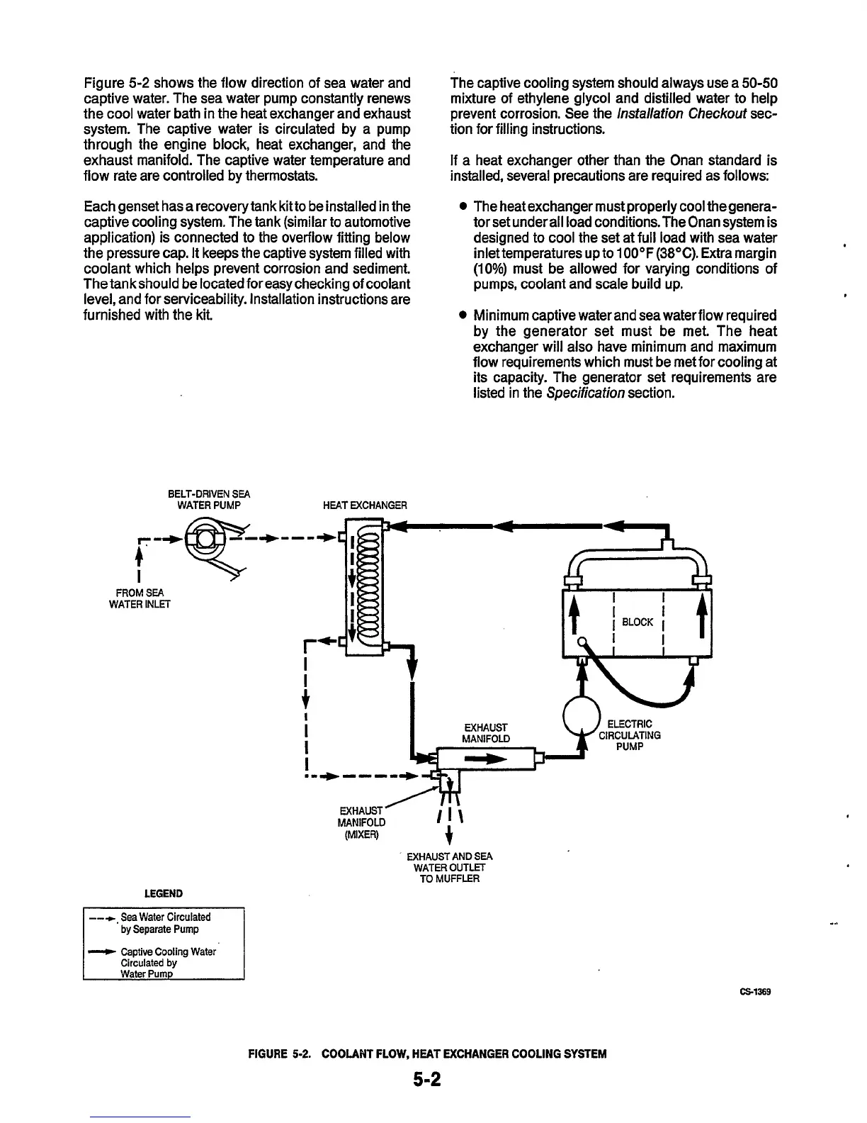
Figure
5-2
shows the flow direction of sea water and
captive water. The sea water pump constantly renews
the cool water bath in the heat exchanger and exhaust
system. The captive water is circulated by a pump
through the engine block, heat exchanger, and the
exhaust manifold. The captive water temperature and
flow rate are controlled
by
thermostats.
Each genset has a recoverytank kit to be installed in the
captive cooling system. The tank (similar to automotive
application) is connected to the overflow fitting below
the pressure cap. It keeps the captive system filled with
coolant which helps prevent corrosion and sediment.
The tankshould be locatedforeasychecking
of
coolant
level, and for serviceability. lnstallation instructions are
furnished with the kit.
BELT-DRIVEN
SEA
WATER PUMP HEAT EXCHANGER
r-
I
FROM
SEA
WATER INLET
The captive cooling system should always use a
50-50
mixture of ethylene glycol and distilled water to help
prevent corrosion. See the
lnstallation Checkout
sec-
tion for filling instructions.
If a heat exchanger other than the Onan standard is
installed, several precautions are required as follows:
The heat exchanger must properly cool thegenera-
tor set under all load conditions.The Onan system is
designed to cool the set at full load with sea water
inlet temperatures up
to
1
OOOF
(38OC).
Extra margin
(10%)
must be allowed for varying conditions of
pumps, coolant and scale build up.
Minimum captive water and sea water flow required
by the generator set must be met. The heat
exchanger will also have minimum and maximum
flow requirements which must be met for cooling at
its capacity. The generator set requirements are
listed in the
Specificafion
section.
r*
I
I
t
I
I
I
I
.-*----
t
MANIFOLD
(MIXER)
EXHAUST AND
SEA
WATER OUTLET
TO
MUFFLER
by Separate Pump
--P
Captive Cooling Water
Circulated by
cs1369
....
FIGURE
5-2.
COOLANT
FLOW, HEAT EXCHANGER COOLING SYSTEM
5-2
 Loading...


