FUEL LINES
The proper installation of fuel lines is very important
Give special attention to the following requirements.
0
All
fuel line materials must meetthe requirementsof
both the USCG and the ABYC.
0
Solid fuel lines must be seamless annealed, double-
flared, and approved for marine installations.
0
Run fuel lines at the top level of tank to a point as
close to the engine as possible to reduce danger of
fuel siphoning should the line break.
areas. This reduces chance of vapor lock.
I
.
0
Keep fuel lines away from hot engine or exhaust
0
Any locked-in torsional stresses must be avoided in
the fuel line.
0
Install a flexiblefuel line meeting USCG requirement
33CFR183.558, and stamped
“USCG
TYPE
A”
between the solid fuel line and engine to absorb
vibration. The line length must be sufficient to pre-
vent binding or stretching due to generator set
movement.
,
FUEL LINE
I
TO
BOAT
I
COMMON BONDING
METALLIC
FUEL
CONDUCTOR
LINE FROM TANK
ES-1891
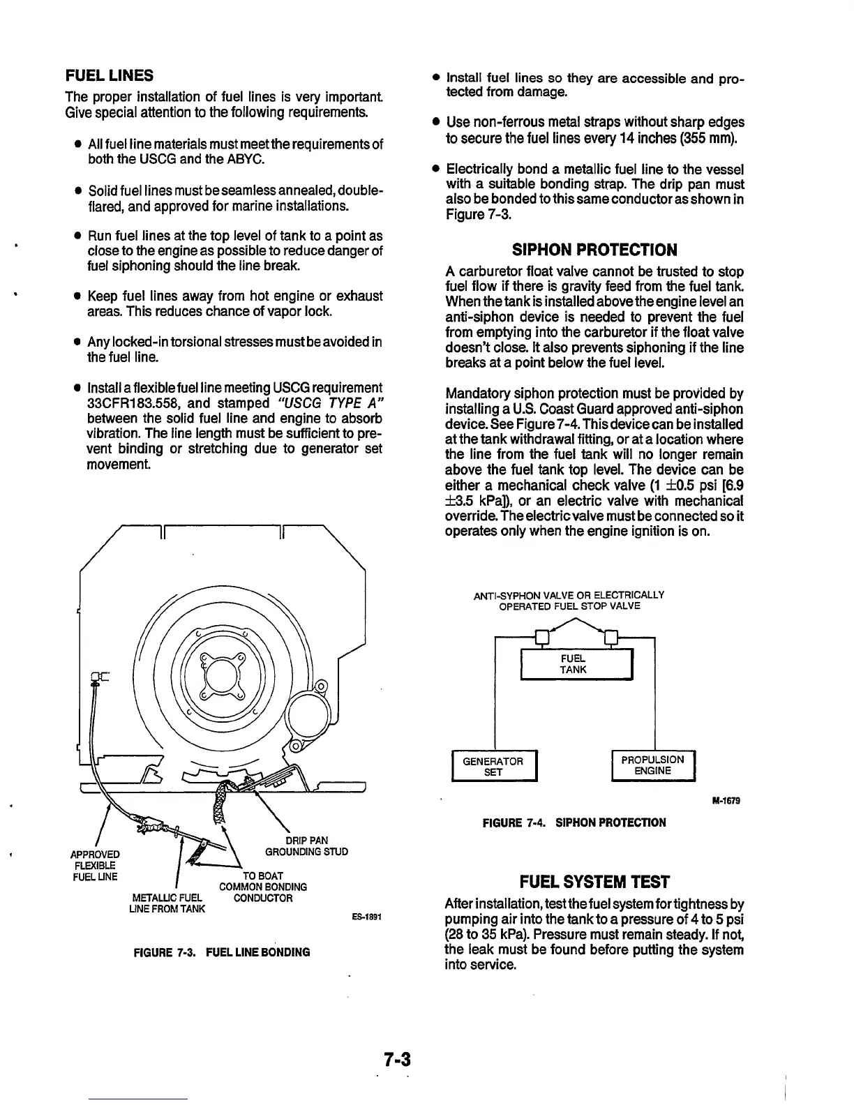
FIGURE 7-3. FUEL LINE BONDING
Install fuel lines
so
they
are
accessible and pro-
tected from damage.
Use non-ferrous metal straps without sharp edges
to secure the fuel lines every
14
inches
(355
mm).
Electrically bond a metallic fuel line to the vessel
with a suitable bonding strap. The drip pan must
also be bonded to thissame conductor asshown in
Figure 7-3.
SIPHON
PROTECTION
A carburetor float valve cannot be trusted to stop
fuel flow if there is gravity feed from the fuel tank.
When the tank is installed above the engine level an
anti-siphon device is needed to prevent
the
fuel
from emptying into the carburetor if the float valve
doesn’t close.
It
also prevents siphoning if the line
breaks at a point below the fuel level.
Mandatory siphon protection must be provided by
installing a
U.S.
Coast Guard approved anti-siphon
device. See Figure
7-4.
This device can be installed
at the tank withdrawal fitting, or at a location where
the line from the fuel tank will no longer remain
above the fuel tank top level. The device can be
either a mechanical check valve
(1
f0.5
psi
[6.9
53.5
kPa]), or an electric valve with mechanical
override. The electricvalve must be connected
so
it
operates only when the engine ignition is on.
ANTISYPHON VALVE OR ELECTRICALLY
OPERATED FUEL STOP VALVE
M-1679
FIGURE
7-4.
SIPHON PROTECTION
FUEL SYSTEM TEST
After installation, test thefuel system fortightness by
pumping air into the tank to a pressure Of
4
to
5
psi
(28 to 35 kPa). Pressure must remain steady. If not,
the leak must be found before putting the system
into service.
7-3
 Loading...


