WHEN
CAM
SHAFT
PROPE
THE
D
ON
DR
AS
INDICATED
CENTER PIN
GOVERNOR C
GOVERNOR
FLY
BAL
U
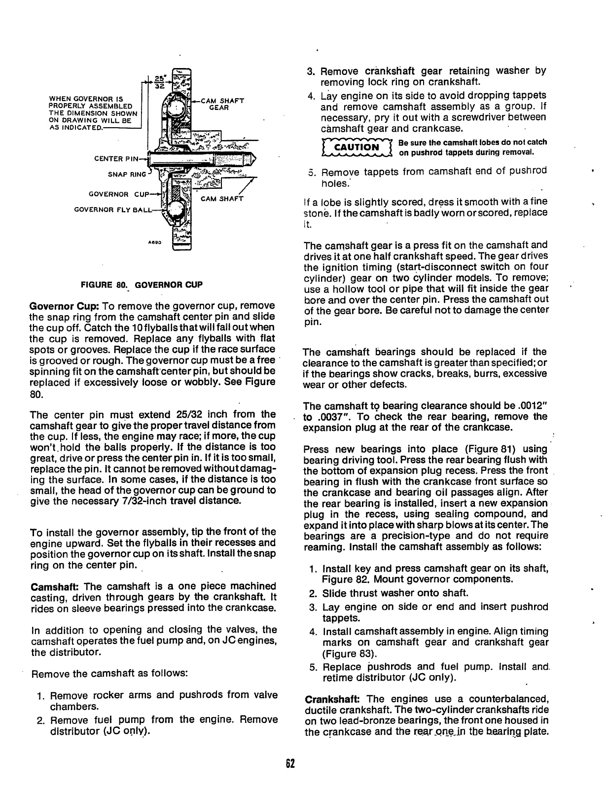
FIGURE
80.
GOVERNOR
CUP
Governor
Cup:
To
remove the governor cup, remove
the snap ring from the camshaft center pin and slide
the cup off. Catch the
10flyballsthatwillfalloutwhen
the cup is removed. Replace any flyballs with flat
spots or grooves. Replace the cup
if
the race surface
is grooved or rough. The governor cup must be a free
'
spinning fit on the camshaft'center pin, but should be
replaced if excessively loose or wobbly. See Figure
80.
The center pin must extend 25/32 inch from the
camshaft gear to give the proper travel distance from
the cup. If less, the engine may race;
if
more, the cup
won't. hold the balls properly. If the distance is too
great, drive or press the center pin in. If
it
is too small,
replace the pin.
It
cannot be removed without damag-
ing the surface.
In
some cases, if the distance is too
small, the head of the governor cup can be ground to
give the necessary 7/32-inch travel distance.
To
install the governor assembly, tip the front of the
engine upward. Set the flyballs
in
their recesses and
position the governor cup on itsshaft. Install thesnap
ring on the center pin.
Camshaft: The camshaft is a one piece machined
casting, driven through gears by the crankshaft.
It
rides on sleeve bearings pressed into the crankcase.
In addition to opening and closing the valves, the
camshaft operates the fuel pump and, on JCengines,
the distributor.
Remove the camshaft as follows:
3. Remove crankshaft gear retaining washer by
removing lock ring on crankshaft.
4.
Lay engine on its side to avoid dropping tappets
and remove camshaft assembly
as
a group.
If
necessary, pry it out with a screwdriver between
camshaft gear and crankcase.
CAUT,ON
Be sure the camshaft lobes
do
not
catch
5.
Remove tappets from camshaft end of pushrod
If
a lobe is slightly scored, dress it smooth with
a
fine
stone. If the camshaft is badly worn or scored, replace
it.
EZ.z-2
on
pushrod tappets during removal.
holes.'
The camshaft gear is a press fit on the camshaft and
drives
it
at one half crankshaft speed. The gear drives
the ignition timing (start-disconnect switch on four
cylinder) gear on two cylinder models. To remove;
use a hollow tool or pipe that will fit inside the gear
hore and over the center pin. Press the camshaft out
of the gear bore. Be careful not to damage the center
pin.
The camshaft bearings should be replaced
if
the
clearance to the camshaft is greater than specified: or
if the bearings show cracks, breaks, burrs, excessive
wear or other defects.
The camshaft to bearing clearance should be .0012"
to
.0037".
To check the rear bearing, remove the
expansion plug at the rear of the crankcase.
Press new bearings into place (Figure 81) using
bearing driving tool. Press the rear bearing flush with
the bottom of expansion plug recess. Press the front
bearing
in
flush with the crankcase front surface
so
the crankcase and bearing oil passages align. After
the rear bearing is installed, insert a new expansion
plug in the recess, using sealing compound, and
expand
it
into place with sharp blows at its center. The
bearings are a precision-type and do not require
reaming. Install the camshaft assembly as follows:
1.
Install key and press camshaft gear
on
its shaft,
2. Slide thrust washer onto shaft.
3. Lay engine on side or end and insert pushrod
tappets.
4.
Install camshaft assembly in engine. Align timing
marks on camshaft gear and crankshaft gear
(Figure 83).
5.
Replace pushrods and fuel pump. Install and.
retime distributor (JC only).
Figure 82. Mount governor components.
.
'*
Remove
rocker
cham be rs.
2.
Remove fuel
pump from the engine. Remove
distributor
(JC
onlv).
and pushrods
from
Crankshaft: The engines
use a counterbalanced,
ductile crankshaft. The two-cylinder crankshafts ride
on two lead-bronze bearings, the front one housed in
the crankcase and the rear-0Qe-h tbe bearing plate.
62
Redistribution or publication of this document,
by any means, is strictly prohibited.
 Loading...


