.
GEAR
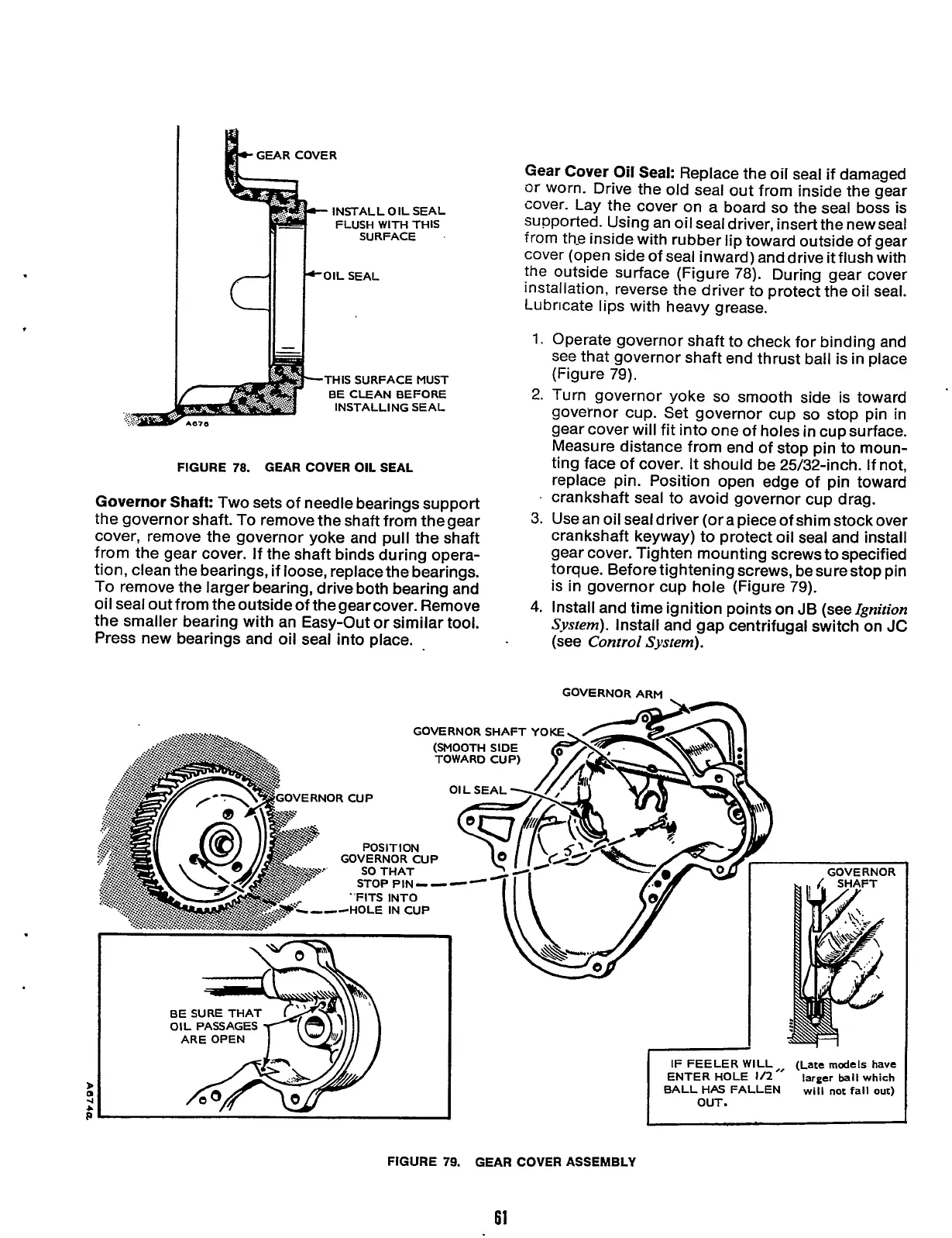
COVER
INSTALL OIL SEAL
FLUSH
WITH
THIS
SURFACE
THIS SURFACE MUST
BE CLEAN BEFORE
INSTALLING SEAL
FIGURE
78.
GEAR COVER OIL SEAL
Governor Shaft:
Two sets of needle bearings support
the governor shaft.
To
remove the shaft from thegear
cover, remove the governor yoke and pull the shaft
from the gear cover. If the shaft binds during opera-
tion, clean the bearings, if loose, replace the bearings.
To
remove the larger bearing, drive both bearing and
oil seal outfrom theoutsideof thegearcover. Remove
the smaller bearing with an Easy-Out or similar tool.
Press new bearings and oil seal into place.
BE SURE THAT
OIL PASSAGES
ARE OPEN
Gear Cover
Oil
Seal:
Replace the oil seal if damaged
or
worn. Drive the old seal out from inside the gear
cover. Lay the cover on a board
so
the seal boss is
supported. Using an oil seal driver, insert the new seal
from th-e inside with rubber lip toward outside of gear
cover (open side of seal inward) and drive
it
flush with
the outside surface (Figure 78). During gear cover
installation, reverse the driver to protect the oil seal.
Lubricate lips with heavy grease.
1.
Operate governor shaft to check for binding and
see
that governor shaft end thrust ball is in place
(Figure 79).
2.
Turn governor yoke
so
smooth side is toward
governor cup. Set governor cup
so
stop pin in
gear cover will fit into one of holes in cup surface.
Measure distance from end of stop pin to moun-
ting face of cover. It should be 25/32-inch.
If
not,
replace pin. Position open edge of pin toward
3.
Use an oil seal driver (or a piece of shim stock over
crankshaft keyway) to protect oil seal and install
gear cover. Tighten mounting screws to specified
torque. Before tightening screws, besurestop pin
is in governor cup hole (Figure 79).
4.
Install and time ignition points on JB (see
Ignition
System).
Install and gap centrifugal switch on
JC
(see
Control System).
.
crankshaft seal to avoid governor cup drag.
GOVERNORARM
IF
FEELER
WILL
ENTER HOLE
112
"
BALL HAS FALLEN
(Late
models
have
larger
ball
which
will
not
fall
out)
OUT.
I
FIGURE
79.
GEAR COVER ASSEMBLY
61
Redistribution or publication of this document,
by any means, is strictly prohibited.
 Loading...


