11
Electrical Connections
Do not connect the battery cables to the battery until
Installation Review and Startup (Page 17) to pre-
vent accidental starting of the genset during
installation.
WARNING
Accidental starting of the genset
can cause severe personal injury or death. Do
not connect the starting battery until Installa-
tion Review and Startup (Page 17).
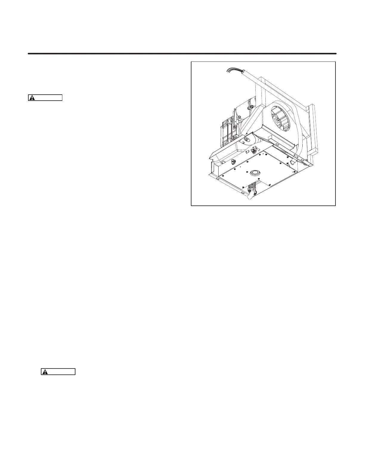
GENERATOR CONNECTIONS
The genset is equipped with 28 inch (715 m) long
AC power output leads in 1/2 inch flexible steel con-
duit (Figure 8). See Figure 9 for typical connections.
If these leads must be replaced by longer leads,
make sure their ampacity, as determined by the
appropriate chart in the National Electrical Code
(NEC), is at least 115 percent of the amps marked
on the genset circuit breaker. (Unless 125° C rated
wiring is available, heavier gauge wiring may be
required to obtain the required ampacity.)
Wiring Methods
Follow the National Electrical Code, especially not-
ing the following:
1. Have a qualified electrician supervise and in-
spect the installation of all AC wiring.
2. Install vibration-proof switches and controls
that won’t open and close circuits when the
vehicle is in motion.
3. Provide ground fault circuit interrupters
(GFCIs)for all convenience power receptacles.
4. Route AC wiring, remote control wiring and fuel
lines separately.
5. Seal all conduit openings into the vehicle inte-
rior to keep out exhaust gas. Apply silicone rub-
ber or an equivalent type of sealant inside and
outside each conduit connector. (Flexible con-
duit is not vapor-tight and will allow exhaust gas
to enter along the wires if not sealed.)
WARNING
EXHAUST GAS IS DEADLY!
Seal all wiring openings into the vehicle
interior to keep out exhaust gas.
FIGURE 8. AC OUTPUT LEADS AND CONDUIT
Redistribution or publication of this document,
by any means, is strictly prohibited.
 Loading...
