Assembly
1.
2.
3.
4.
5.
6.
7.
When installing a new diaphragm, soak it in fuel
before assembling. Insert diaphragm spring and
soaked diaphragm into pump body.
Insert link and rocker arm into body and hook it
over diaphragm pull rod. Align rocker arm with
rocker arm pin hole and drive in pin. The priming
lever must be in position shown in Figure30 when
installing rocker arm.
Compress rocker spring and install between the
body and rocker arm.
Assemble cover to body, with notch marks lined
up. Install screws but do not tighten.
Fuelleakageis a fireand expio-
n
sion hazard fhaf might cause
severe personal injury or death. Use care when
reassembling fuel pump. All parts must align per-
fecfly or pump will leak fuel.
Push rockerarm in onefull strokeand hold
in
this
position to flex diaphragm.
Tighten cover screws alternately and securely,
then release rocker arm.
Install pump on the engine and repeat pressure
test.
INJECTION NOZZLES
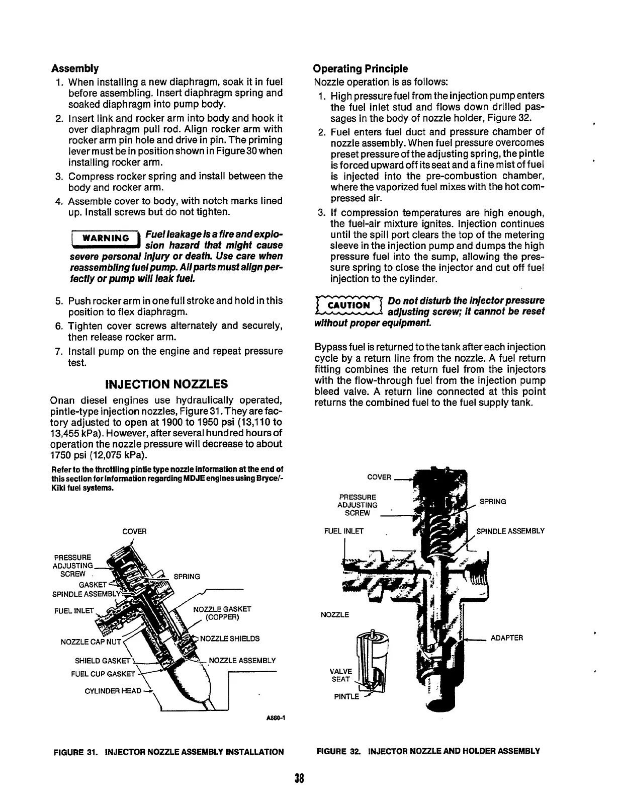
Onan diesel engines use hydraulically operated,
pintle-type injection nozzles, Figure 31. They are fac-
tory adjusted to open at 1900 to
1950
psi
(13,110
to
13,455
kPa). However, after several hundred hours of
operation the nozzle pressure will decrease to about
1750
psi
(1
2,075 kPa).
Refer to the throttling pintle type nozzle information at the end of
thissection for information regarding MDJEenginesusing Bryce/-
Kiki fuel systems.
COVER
PRESSURE
A&
GASKET
:
SPINDLE
ASSEMBLY
NOZZLE
CAP
NUT-(
7
SHIELD GASKET
f-
F
FUEL
CUP
GASKET
CYLINDER
HEAD
A,
7
\
Ul
A0aQ-j
FIGURE
31.
INJECTOR NOZZLE ASSEMBLY INSTALLATION
Operating Principle
Nozzle operation
is
as follows:
1.
2.
3.
High pressure fuel from the injection pump enters
the fuel inlet stud and flows down drilled pas-
sages in the body of nozzle holder, Figure 32.
Fuel enters fuel duct and pressure chamber of
nozzle assembly. When fuel pressure overcomes
preset pressure of the adjusting spring, the pintle
is forced upward off its seat and a fine mist of fuel
is injected into the pre-combustion chamber,
where
the
vaporized fuel mixes with the hot com-
pressed air.
If compression temperatures are high enough,
the fuel-air mixture ignites. Injection continues
until the spill port clears the top of the metering
sleeve in the injection pump and dumps the high
pressure fuel into
the
sump, allowing the pres-
sure spring to close the injector and cut off fuel
injection to the cylinder.
Do
not disfurb fhe injector pressure
adjusfing screw;
it
cannof be reset
without proper equipment.
Bypass fuel is returned to the tank after each injection
cycle by a return line from the nozzle. A fuel return
fitting combines the return fuel from the injectors
with the flow-through fuel from the injection pump
bleed valve. A return line connected at this point
returns the combined fuel to the fuel supply tank.
.
FIGURE
32.
INJECTOR NOZZLE AND HOLDER ASSEMBLY
38
Redistribution or publication of this document,
by any means, is strictly prohibited.