6.
Manually operate fuel transfer pump (Figure
53)
until
fuel, free of
air,
flowsfrom
open
end
of
No.
1
injection
line
into
container
(Figure
51).
WORK TRANSFER
PUMP
PRIMING
LEVER
UNTIL
CONTAINER
quL,
FUEL
FLOWS INTO
11
LOWEST
POSITION
An3n
Rev
FIGURE 53.
OPERATING
TRANSFER
PUMP MANUALLY
7.
Continue operating transfer pump while assistant
rotates flywheel slowly in clockwise direction.
Stop flywheel rotation at exact point that fuel
stops flowing from
No.
1
injection line (one drop
in
2
to
5
seconds is allowed). This point is the
injection pump plunger port closing, regardless
of flywheel position.
Timing is correct if port closign occurs when PC
mark on flywheel aligns with timing pointer (Fig-
ure
52).
If the marks do not line up, timing is either
early or late and the timing button must be
changed.
If Step? indicates port closing is incorrect (late or
early) proceed as follows (See Examples):
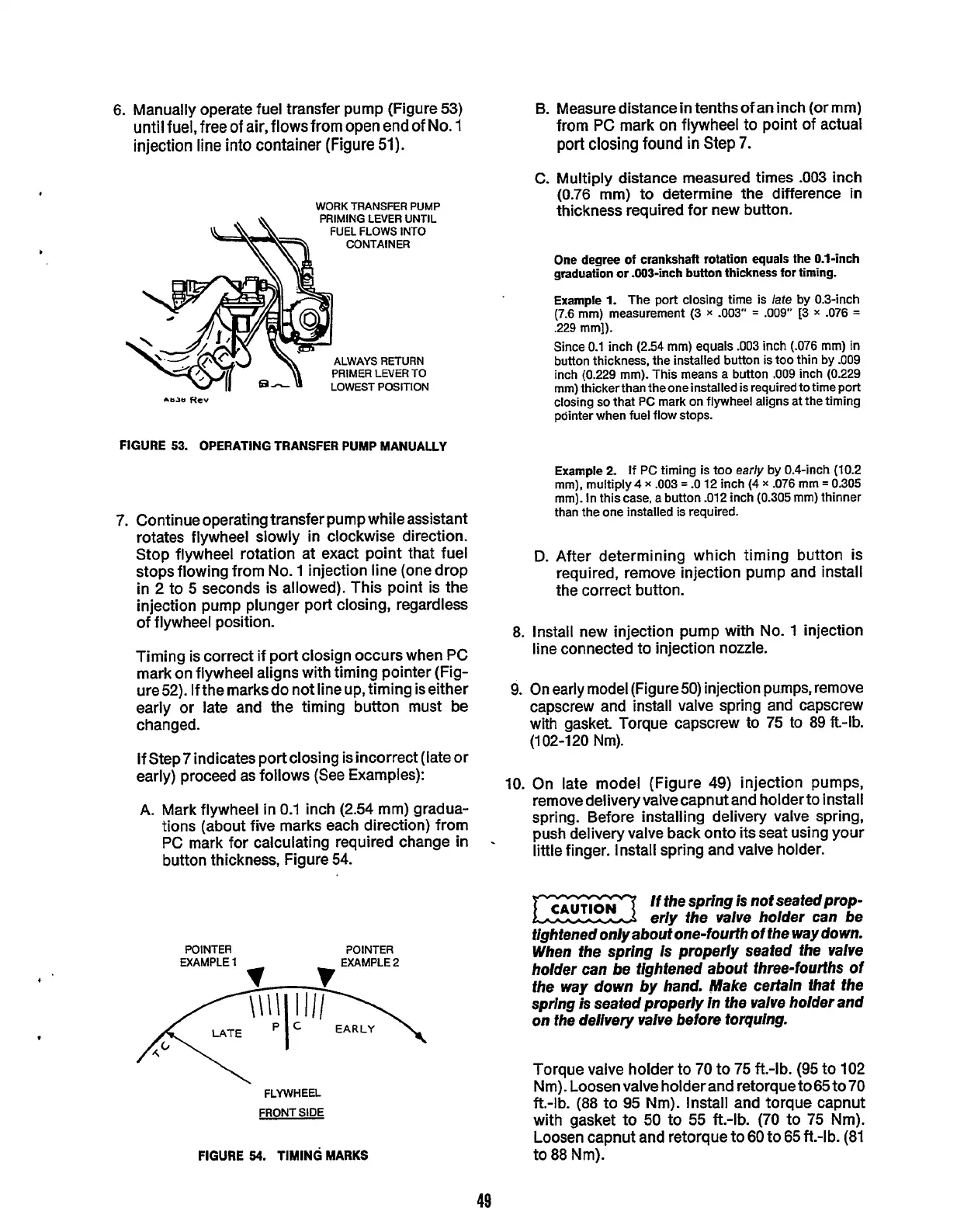
A. Mark flywheel
in
0.1
inch
(2.54
mm) gradua-
tions (about five marks each direction) from
PC mark for calculating required change
in
button thickness, Figure
54.
.
POINTER
POINTER
EXAMPLE
1
FLYWHEEL
FRONT
SIDE
FIGURE
54.
TIMING
MARKS
8.
Measure distance
in
tenths of an inch (or mm)
from PC mark on flywheel to point of actual
port closing found
in
Step
7.
C.
Multiply distance measured times
.003
inch
(0.76
mm) to determine the difference
in
thickness required for new button.
One
degree
of
crankshaft rotation
equals
the 0.1-inch
graduation
or
.OO3-inch button thickness
for
timing.
Example
1.
The port closing time is
late
by 0.3-inch
(7.6
mm)
measurement
(3
x
-003"
=
.009"
[3
x
.076
=
.229
mm]).
Since
0.1
inch
(2.54
mm)
equals
.003
inch
(.076
mm)
in
button thickness, the installed button is too thin by
.009
inch
(0.229
mm).
This means a button
.009
inch
(0.229
mm) thickerthan theoneinstalled is required to time port
closing
so
that PC mark on flywheel aligns at the timing
pointer when fuel flow stops.
Example
2.
If
PC timing
is
too
early
by 0.4-inch
(10.2
mm), multiply4
x
.003
=
.O
12
inch
(4
x
.076
mm
=
0.305
mm). In this case,
a
button
.012
inch
(0.305
mm) thinner
than the one installed
is
required.
D.
After determining which timing button is
required, remove injection pump and install
the correct button.
8.
Install new injection pump with
No.
1
injection
line
connected to injection nozzle.
9.
On
early model (Figure50) injection pumps, remove
capscrew and install valve spring and capscrew
with gasket. Torque capscrew to
75
to
89ft-lb.
(102-120
Nm).
10.
On late model (Figure
49)
injection pumps,
remove delivery valve capnut and holder to install
spring. Before installing delivery valve spring,
push delivery valve back onto its seat using your
little
finger. Install spring and valve holder.
If
the spring
is
not seafedprop-
eriy the valve holder can be
tightened only about one-fourth of the way down.
When fhe spring is properly seated the valve
holder can be tightened about fhree-fourths of
the way down by hand. Make certain that the
spring
is
seated properly in the valve holder and
on fhe delivery valve before torquing.
Torque valve holder to
70
to
75
ft.-lb.
(95
to
102
Nm). Loosen valve holder and retorque to
65
to
70
ft.-lb.
(88
to
95
Nm). Install and torque capnut
with gasket to
50 to
55
ft.-lb.
(70
to
75
Nm).
Loosen capnut and retorque to
60
to
65
it.-lb.
(81
to
88
Nm).
49
Redistribution or publication of this document,
by any means, is strictly prohibited.