BRYCE/KIKI
FUEL
SYSTEM
The Bryce or
Kiki
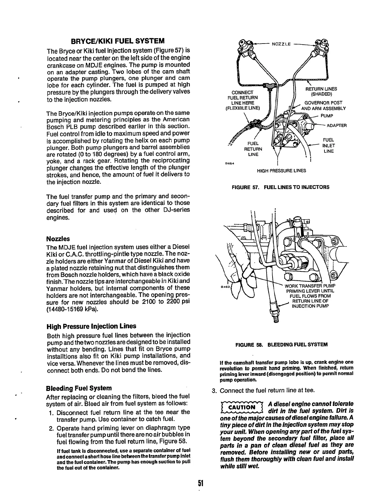
fuel injection system (Figure57) is
located near the center on the left side of the engine
crankcase on
MDJE
engines. The pump is mounted
on an adapter casting. Two lobes of the cam shaft
operate the pump plungers, one plunger and cam
lobe for each cylinder. The fuel is pumped at high
pressure by
the
plungers through the delivery valves
The Bryce/Kiki injection pumps operate on the same
pumping and metering principles as the American
Bosch PLB pump described earlier in this section.
Fuel control from idle to maximum speed and power
is accomplished by rotating
the
helix on each pump
plunger. Both pump plungers and barrel assemblies
are rotated
(0
to 180 degrees) by a fuel control arm,
yoke, and a rack gear. Rotating the reciprocating
plunger changes the effective length of the plunger
strokes, and hence, the amount of fuel
it
delivers to
the injection nozzle.
The fuel transfer pump and
the
primary and secon-
dary fuel filters in this system are identical to those
described for and used on the other DJ-series
engines.
4
to the injection nozzles.
FUEL RETURN
(FLEXIBLE LINE)
GOVERNOR
POST
ARM ASSEMBLY
HIGH
PRESSURE LINES
FIGURE
57.
FUEL LINES
TO
INJECTORS
Nozzles
The
MDJE
fuel injection system uses either a Diesel
Kiki or
C.A.C.
throttling-pintle type nozzle. The noz-
zle
holders are either Yanmar of Diesel Kiki and have
a plated nozzle retaining nut that distinguishes them
from Bosch nozzle holders, which have a black oxide
finish.The nozzle tipsare interchangeable in Kiki and
Yanmar holders, but internal components of these
holders are not interchangeable. The opening pres-
sure for new nozzles should be
2100
to 2200 psi
(14480-15169 kPa).
High Pressure Injection Lines
Both high pressure fuel lines between the injection
pump and the two nozzles are designed to be installed
without any bending. Lines that fit on Bryce pump
installtions also fit on Kiki pump installations, and
vice versa. Whenever the lines must be removed, dis-
connect both ends. Do not bend the lines.
Bleeding Fuel
System
After replacing or cleaning the filters, bleed the fuel
system of air. Bleed air from fuel system as follows:
1.
Disconnect fuel return line at the tee near the
transfer pump. Use container to catch fuel.
2.
Operate hand priming lever on diaphragm type
fuel transfer pump until there are no air bubbles in
fuel flowing from the fuel return
line,
Figure
58.
If
fuel tank is disconnected, use
a
separate container
of
fuel
and connect
a
short hose line between the transfer pump inlet
and the fuel container. The pump has enough suction to pull
the fuel out
of
the container.
PRIMING
LEVER UNTIL
FUEL FLOWS FROM
RETURN LINE OF
INJECTION PUMP
FIGURE
58.
BLEEDING FUEL
SYSTEM
If
the camshaft transfer pump lobe
is
up,
crank engine one
revolution
to
permit hand priming. When finished, return
priming lever inward (disengaged position)
to
permit normal
pump operation.
3.
Connect the fuel return line at tee.
A
diesel engine cannot tolerate
dirt In the fuel system.
Dirt
is
one
of
the major causes
of
diesel engine failure.
A
tiny piece
of
dirt
in
the injection system may
stop
your unit. When opening any part
of
the fuel sys-
tem beyond the secondary fuel filter, place
all
parts
in
a
pan
of
clean diesel fuel as they are
removed. Before insfalling new
or
used
parfs,
flush
them thoroughly with clean fuel and
insfall
while
still
wet.
51
Redistribution or publication of this document,
by any means, is strictly prohibited.