BRYCE/KIKI FUEL INJECTION PUMPS
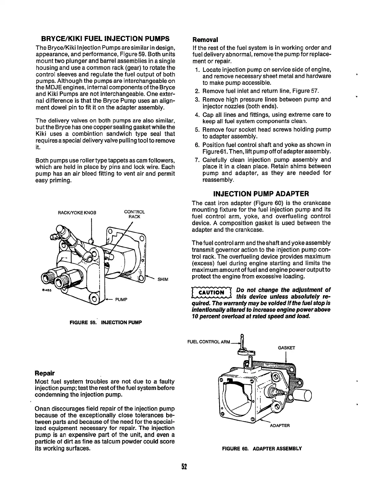
The Bryce/Kiki Injection Pumps aresimilar in design,
appearance, and performance, Figure
59.
Both units
mount two plunger and barrel assemblies in asingle
housing and use a common rack (gear) to rotate the
control sleeves and regulate the fuel output of both
pumps. Although the pumps are interchangeable on
the
MDJE
engines, internal components of the Bryce
and Kiki Pumps are not interchangeable. One exter-
nal difference is that the Bryce Pump uses an align-
ment dowel pin to fit
it
on the adapter assembly.
The delivery valves on both pumps are also similar,
but the Bryce has one copper sealing gasket whilethe
Kiki uses a combintion sandwich type seal that
requires a special deliveryvalve pulling tool to remove
it.
Both pumps use roller type tappets as cam followers,
which are held
in
place by pins and lock wire. Each
pump has an air bleed fitting to vent air and permit
easy priming.
RACKNOKE
KNOB
CONTROL
RACK
I
SHIM
Removal
If the rest of the fuel system is in working order and
fuel deliveryabnormal, remove the pump for replace-
ment
or
repair.
*
1.
2.
3.
4.
5.
6.
7.
Locate injection pump on service side of engine,
and remove necessary sheet metal and hardware
to make pump accessible.
Remove fuel inlet and return line, Figure
57.
Remove high pressure lines between pump and
injector nozzles (both ends).
Cap all lines and fittings, using extreme care to
keep all fuel system components clean.
Remove four socket head screws holding pump
to adapter assembly.
Position fuel control shaft and yoke as shown in
Figure61. Then, lift pump off of adapter assembly.
Carefully clean injection pump assembly and
place
it
in a clean place. Retain shims between
pump and adapter, as they are needed for
reassem b
I
y.
INJECTION PUMP ADAPTER
The cast iron adapter (Figure
60)
is
the
crankcase
mounting fixture for the fuel injection pump and its
fuel control arm, yoke, and overfueling control
device.
A
composition gasket is used between the
adapter and the crankcase.
Thefuel control arm and theshaft and yokeassembly
transmit governor action to the injection pump con-
trol rack. The overfueling device provides maximum
(excess) fuel during engine starting and limits the
maximum amount of fuel and engine power output to
protect the engine from excessive loading.
Do
nof change the adjusfmenf of
Ezx
this device unless absolutely re-
quired. The warranty may be voided if the fuel stop
is
infenfionally altered to increase engine power above
70
percenf overload af rafed speed and load.
CAUT,ON
FIGURE
59.
INJECTION PUMP
FUEL
CONTROL
ARM
GASKET
I
Repair
Most fuel system troubles are not due to a faulty
injection pump; test the rest of the fuel system before
condemning the injection pump.
Onan discourages field repair of the injection pump
because of the exceptionally close tolerances be-
tween parts and because of the need for the special-
ized equipment necessary for repair. The injection
pump is an expensive part of
the
unit, and even a
particle of dirt as fine as talcum powder could score
its working surfaces.
-
ADAPTER
FIGURE
60.
ADAPTER ASSEMBLY
52
Redistribution or publication of this document,
by any means, is strictly prohibited.