7.
Removegear, spring
set
and lever assembly from
front bracket. Note direction
in
which
the
lever
assembly
is
installed.
8.
Push pinion gear and stopper down and remove
retaining ring. Remove stopper, pinion gear,
spring, and pinion shaft assembly.
9.
Inspect
ball
bearings.
If
they are rough
or
noisy
when rotated replace them. The front bearing
is
not replaceable and must
be
replaced with the
bracket.
SOLENOID
TERMINAL
"M'
BEARING
(RETAIN
I
NG
RING)
BRUSH
FHAME HOLDER
ASSEMBLY ASSEMBLY
xw-1255
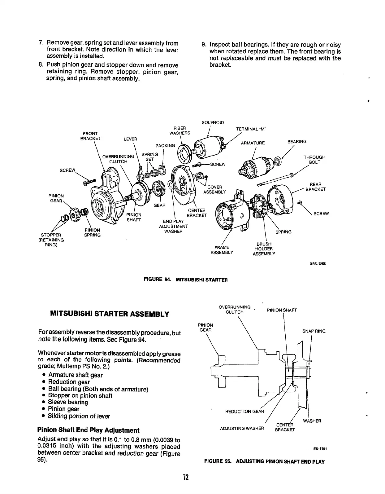
FIGURE
94.
MlTSUBlSHl
STARTER
oVERRUNNING
-
PINION SHAFT
MlTSUBlSHl STARTER ASSEMBLY
CLUTCH
PIN
GE
For
assembly reverse the disassembly procedure, but
note
the following
items.
See
Figure
94.
Whenever starter motor
is
disassembled apply
grease
to
each
of
the following points. (Recommended
grade: Multemp
PS
No.
2.)
Armature
shaft
gear
Reduction gear
Ball bearing (Both ends
of
armature)
Stopper on pinion
shaft
Sleeve bearing
Sliding portion
of
lever
Pinion gear
'
REDUCTION GE
Pinion
Shaft
End
Play
Adjustment
Adjust end play
so
that
it
is
0.1
to
0.8
mm
(0.0039
to
0.031
5
inch) with the adjusting washers placed
between
center
bracket
and
reduction
gear
(Figure
ES-1191
95).
FIGURE
95.
ADJUSTING PINION
SHAFT
END
PLAY
,
72
Redistribution or publication of this document,
by any means, is strictly prohibited.
 Loading...

