t
and
over
the cooling fins
and surfaces
of the eneine.
Heated
air
is expelled
through
a single
discharge
and
away from
the
unit and
installatton
area.
LOCATION
The
compartment
itself should
be of vapor
tight
design
and
completely
independent
of living quarters.
The
interior
Iining should
be fireproof.
A
sheet
metal cover-
ed
compartment
may be readily
sealed
and
lends
itself
easily
to
treatment.
The set
may
have to
be removed
fot service,
so
nrake the door
large
enough
to facilitate
removal
of the
unit,
The
compartment
location
is
determined
by
physical
size,
access
opening and
most
importalt,
best mounting
support.
Allow
2" clearance
on
a1l
sides
of the
unit
for
rocking
on
mounts.
POSITIONING
The following
should
be
considered for
accessibility
when
mounting
the unit
in a compartment.
(Position
so
operating
instructions
and
nameplate are
visible
and/or
install
an accessible
nameplate. data
decal
or sticker.
)
I.
Make
air
discharge
duct as short
as
possible.
Position so exhaust
heated air is
flot
drawn
into
cool air
inlet.
2, Air
cleaner should
be easy to lemove
and service.
3.
Battery
or
batteries
must
be accessible for service.
4.
Oil
fill
tube cap should
be easy to
reach.
5.
The
control
box switch should
be
visible.
6. Provide space for
muffler.
7.
Oi1
drain should
be readily accessible.
8.
Cylindet
head should
be readily accessible
for
servtce.
9. Rope stait
sheave should
be accessible.
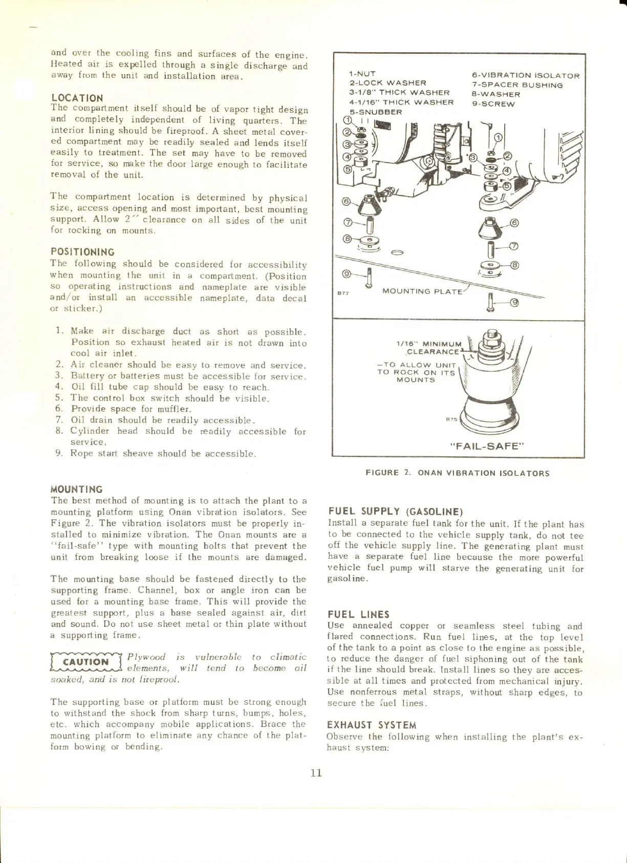
MOUNTING
The best method of mounting
is
to attach the plant
to a
.nounting
platfotm
using Onan vibration isolators. See
Figure 2. The
vibration isolators must be
propetly
in-
stalled
to minirnize vibtation. The
Onan mou[ts
are a
"fail-safe"
type with
mounting bolts that
prevent
the
unit
from
breaking loose if the
mounts
are damaged.
The
mounting base
should be
fastened directly to the
supporting ftame. Channel,
box or angle iron
can
be
used
for
a mounting base
ftame.
This will
provide
the
greatest
support,
plus
a base sealed against air, dirt
and
sound. Do
not use
sheet
metal or
thin
Dlate
without
a supporting frame.
Plywood is vulnetable to climatic
elerrenls,
will
tend to become oil
s<>aked, and is
not
[ireprool.
The supporting base or
platform
must be
strong enough
to withstand the shock from
sharp
turns, bumps, holes,
etc. which accompany mobile applications. Brace the
mounting
platform to eliminate any chance of the
plat-
form bowing or bendin
g.
FIGURE
2.
ONAN VIERATION
ISOLATORS
FUEL
SUPPLY
(GASOLINE)
Install a separate
fuel tank
for the
unit.
If
the plant
has
to be connected
to
the vehicle
supply
tank, do
not
tee
off the
vehicle supply
line.
The
generatiflg
plant
rnust
have a separate
fuel
line
because
the more powerful
vehicle
fuel pump
will starve
the generating
unit for
gasoline.
FUEL LINES
Use
annealed copper
ot seamless steel
tubing and
flated
connections.
Run fuel
lines, at the
top level
of the tank
to a
point
as close
to the engine as possible,
to reduce the danger
oI
fuel
siphoning
out of the tank
if the
line
should
break.
Install lines
so
they are
acces-
sible at all times ard protected from
mechanical injury.
Use nonferrous metal
sttaps,
without sharp
edges,
to
secure
the
fuel
lines.
EXHAUST
SYSTEM
Observe the
following
when
installing the
plant's
ex-
haust system:
6.VIBRATION ISOLATOR
7-SPACER
BUSHING
A-v\/ASHER
9-SCREW
_TO
ALLOW
U NIT
TO
ROCK
ON ITS
MOUNTS
..FAIL-SAFE''
11
 Loading...


