Linkage: The engine starts at wide open throttle.
Rotate the ball joint housing to adjust the length of the
linkage connecting the governor arm to the throttle
arm.
Adjust the length so that with the engine stopped
and the carburetor wide open, the ball joint housing is
even with the governor arm ball joint. This setting
allows immediate control by the governor after star-
ting and synchronizes travel of the governor arm and
the throttle shaft.
Speed Adjustment: The tension applied to the gover-
nor spring determines the speed at which the engine
operates: Increasing spring tension increases engine
speed;
decreasing tension decreases engine speed.
The no-load speed of the engine should be slightly
higher than the speed requirements of the connected
load.
For example: lf the connected load is to turn at 1800
rpm,
set the no-load speed of the engine at 1875 rpm.
Check the speed with a tachometer.
If the engine needs a speed adjustment, turn the
speed adjusting nut in to increase the speed or out to
decrease the speed.
The engine speed droop from no-load to full-load
should be not less than 60 rpm. Check the engine
speed with no-load connected and again after
con-
necting to full
load.
Sensitivity Adjustment: After adjusting thecarburetor
and the governor, adjust the governor sensitivity
(Figure 33). Sensitivity affects the rpm from no load to
full
load.
Moving the governor spring closer to the
shaft makes the governor more sensitive to load
change and decreases the speed change from no load
to full
load.
Observing a frequency meter, adjust the
sensitivity for as close a cycle range as possible
without hunting.
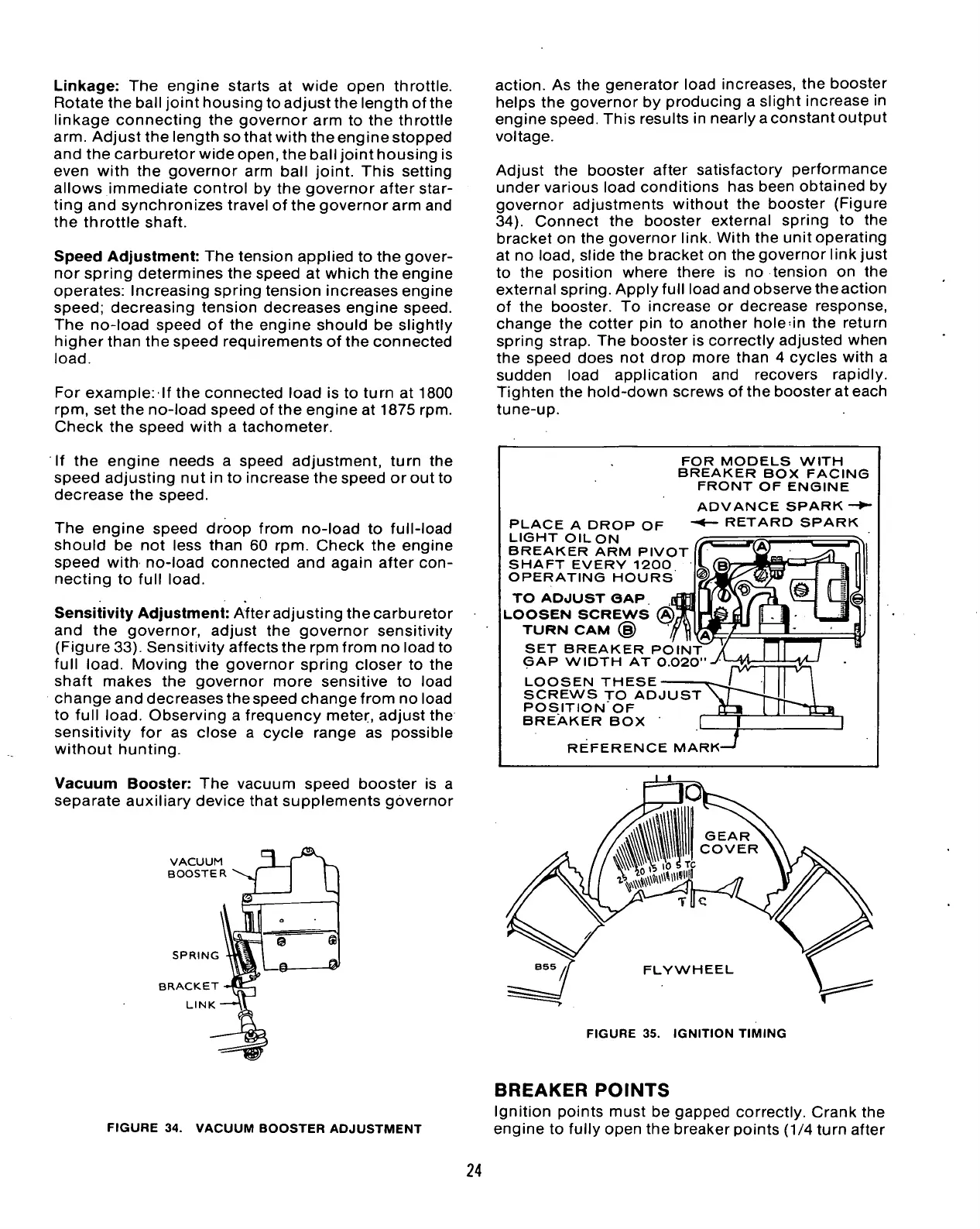
Vacuum Booster: The vacuum speed booster is a
separate auxiliary device that supplements governor
VACUUM I
BOOSTERS
r
'
SPRING
BRACKET
LINK
1
o
@ <
_© 1
action.
As the generator load increases, the booster
helps the governor by producing a slight increase in
engine speed. This results in nearly a constant output
voltage.
Adjust the booster after satisfactory performance
under various load conditions has been obtained by
governor adjustments without the booster (Figure
34).
Connect the booster external spring to the
bracket on the governor link. With the unit operating
at no
load,
slide the bracket on the governor link just
to the position where there is no tension on the
external spring. Apply full load and observe theaction
of the booster. To increase or decrease response,
change the cotter pin to another hole^in the return
spring strap. The booster is correctly adjusted when
the speed does not drop more than 4 cycles with a
sudden load application and recovers rapidly.
Tighten the hold-down screws of the booster at each
tune-up.
PLACE A DROP OF
LIGHT OILON
BREAKER ARM PIVOT
SHAFT EVERY 1200
OPERATING HOURS
TO ADJUST GAP.
LOOSEN SCREWS
TURN CAM (§)
SET BREAKER POINT
GAP WIDTH AT 0.020"
LOOSEN THESE
SCREWS TO ADJUST
POSITION OF
BREAKER BOX
FOR MODELS WITH
BREAKER BOX FACING
FRONT OF ENGINE
ADVANCE SPARK—
RETARD SPARK
REFERENCE MARK
FIGURE 35. IGNITION TIMING
FIGURE 34. VACUUM BOOSTER ADJUSTMENT
BREAKER
POINTS
Ignition points must be gapped correctly. Crank the
engine to fully open the breaker points (1/4 turn after
24
 Loading...


