5. Restrictions imposed
shutters
or
filters
by screens, louvers,
6. Prevailing wind direction.
Remember that
a
required volume
of air
must reach
the unit, absorb
the
heat,
and be
discharged away
from
the
installation. Pressure cooled units need
an
inlet vent with
an
unrestricted opening
of at
least two
square feet.Use auxiliary fans
to
increase
air
flow
to
units installed
in
small, poorly ventilated rooms.
The
fan size
and
location should
be
such that the
air
inlet
to
the
engine does
not
exceed 120°
F
when running
at
full rated
load.
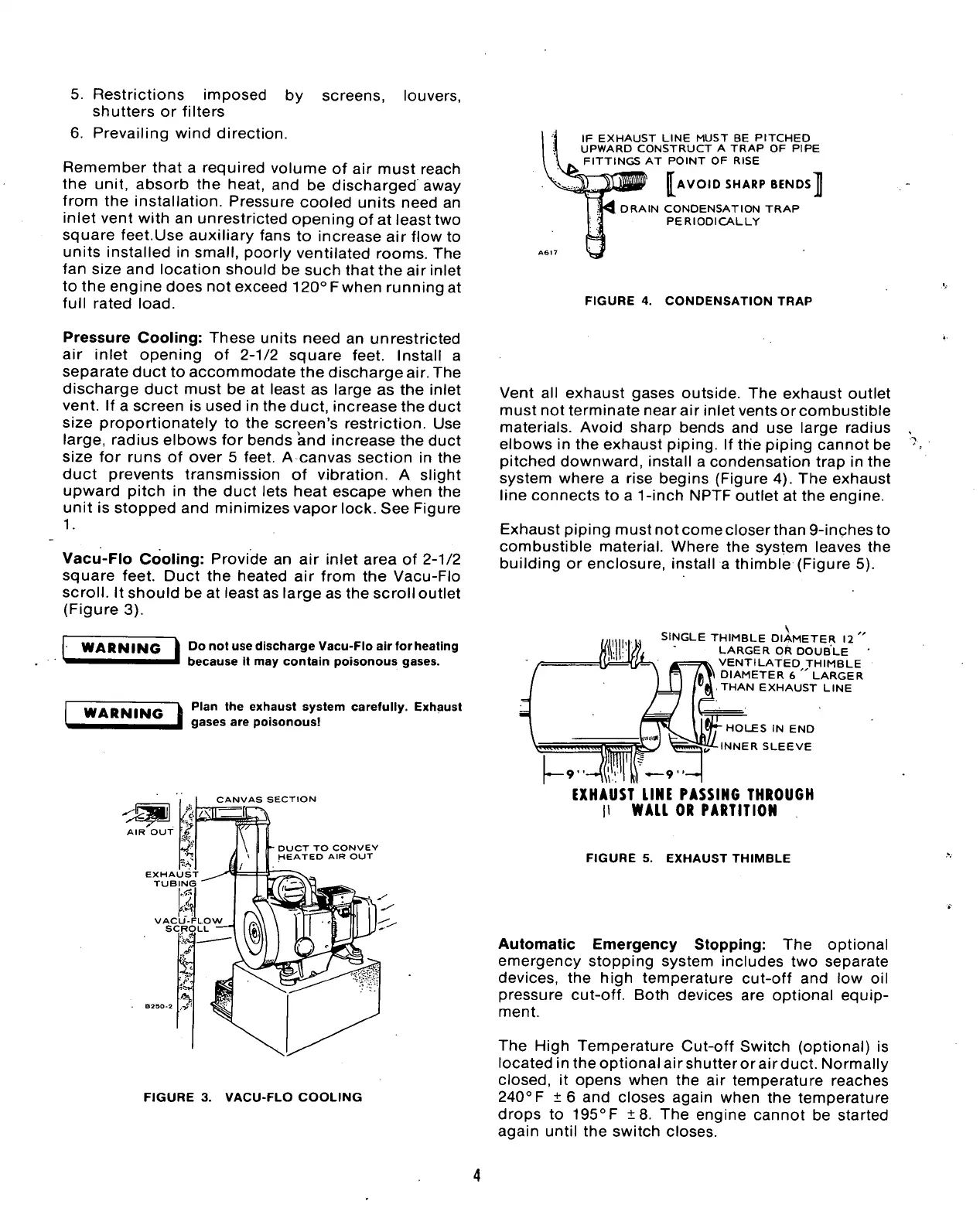
IF EXHAUST LINE MUST
BE
PITCHED
UPWARD CONSTRUCT
A
TRAP
OF
PIPE
FITTINGS
AT
POINT
OF
RISE
AVOID SHARP BENDS
4 DRAIN CONDENSATION TRAP
PERIODICALLY
]
FIGURE
4.
CONDENSATION TRAP
Pressure Cooling: These units need
an
unrestricted
air inlet opening
of 2-1/2
square feet. Install
a
separate duct
to
accommodate the discharge air. The
discharge duct must
be at
least
as
large
as the
inlet
vent.
If a
screen
is
used
in
the duct, increase the duct
size proportionately
to the
screen's restriction.
Use
large,
radius elbows
for
bends and increase
the
duct
size
for
runs
of
over
5
feet.
A
canvas section
in the
duct prevents transmission
of
vibration.
A
slight
upward pitch
in the
duct lets heat escape when
the
unit
is
stopped
and
minimizes vapor lock. See Figure
1.
Vacu-Flo Cooling: Provide
an air
inlet area
of
2-1/2
square feet. Duct
the
heated
air
from
the
Vacu-Flo
scroll.
It
should
be
at
least as large as the scroll outlet
(Figure
3).
WARNING
Do not use discharge Vacu-Flo
air
for heating
because
it
may
contain poisonous gases.
WARNING
Plan
the
exhaust system carefully. Exhaust
gases
are
poisonous!
CANVAS
SECTION
DUCT TO CONVEY
HEATED
AIR
OUT
FIGURE
3.
VACU-FLO COOLING
Vent
all
exhaust gases outside.
The
exhaust outlet
must not terminate near
air
inlet vents or combustible
materials. Avoid sharp bends
and use
large radius
elbows
in
the
exhaust piping.
If
the piping cannot
be
pitched downward, install
a
condensation trap
in the
system where
a
rise begins (Figure 4).
The
exhaust
line connects
to a
1-inch
NPTF outlet
at
the
engine.
Exhaust piping mustnotcomecloserthan9-inchesto
combustible material. Where
the
system leaves
the
building
or
enclosure, install
a
thimble (Figure
5).
SINGLE THIMBLE DIAMETER
12
"
LARGER
OR
DOUBLE
VENTILATED THIMBLE
'•W DIAMETER
6 "
LARGER
THAN EXHAUST LINE
HOLES
IN END
INNER SLEEVE
EXHAUST
LINE
PASSING
THROUGH
|l
WALL
OR PARTITION
FIGURE
5.
EXHAUST THIMBLE
Automatic Emergency Stopping:
The
optional
emergency stopping system includes
two
separate
devices,
the
high temperature cut-off
and low oil
pressure cut-off. Both devices
are
optional equip-
ment.
The High Temperature Cut-off Switch (optional)
is
located in the optional air shutter or air duct. Normally
closed,
it
opens when
the air
temperature reaches
240°
F
±6 and
closes again when
the
temperature
drops
to
195°F
±8. The
engine cannot
be
started
again until
the
switch closes.
 Loading...


