®-
9°°
ELBOW
®
^
~
»—NIPPLE®
JL^REDUCING BUSHINOQ
(OPTIONAL!
GAS REGULATOR
@
GAS HOSE
(fi)
HALF PIPE NIPPLE©
EARLIER MODELS
HAD ADDITIONAL
OUTLET HERE WITH
3A" PIPE PLUG.
^ PIPE PLUG
8
-ADJUSTING SCREW
©
VENT ©-INSTALL AFTER ADJUSTMENT
MANUAL SHUT
OFF
GAS SOLENOID VALVE
4 GAS SUPPLY LINE
•
DRY
FUEL
FILTER
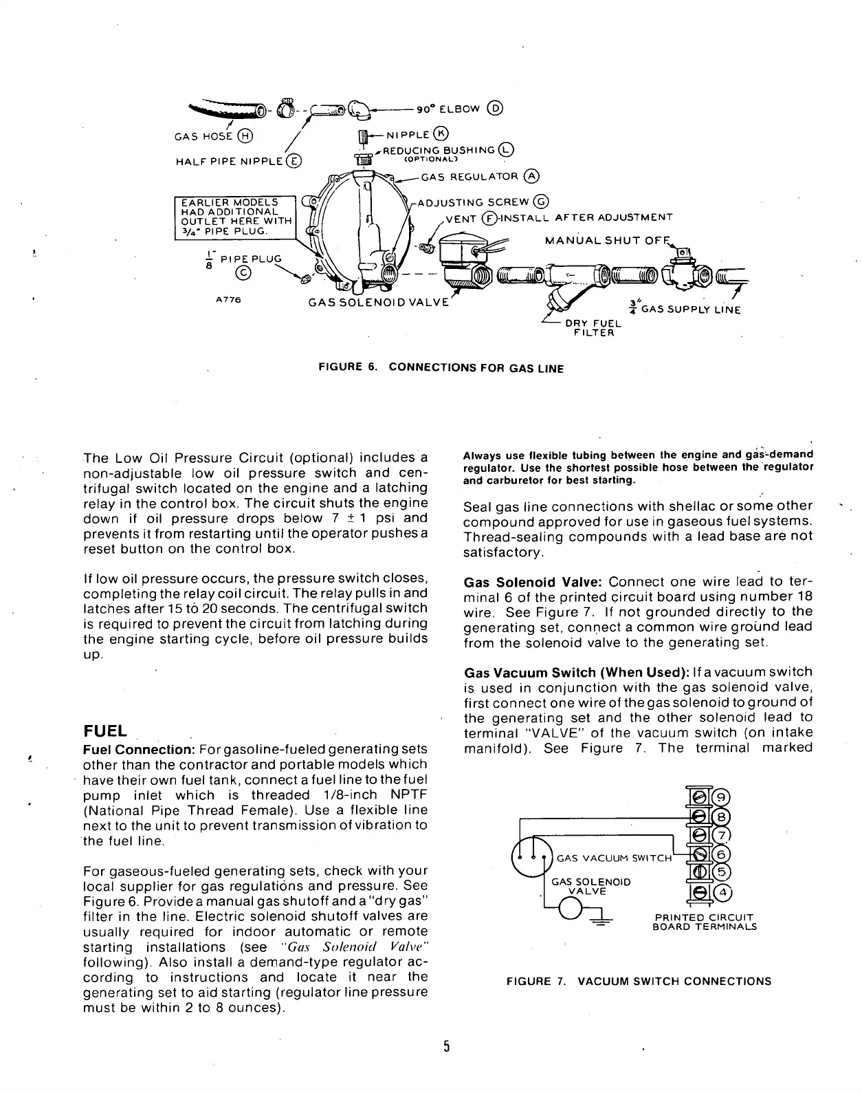
FIGURE
6.
CONNECTIONS
FOR GAS
LINE
The
Low Oil
Pressure Circuit (optional) includes
a
non-adjustable
low oil
pressure switch
and
cen-
trifugal switch located
on the
engine and
a
latching
relay
in the
control box. The circuit shuts the engine
down
if oil
pressure drops below
7 ±
1
psi and
prevents
it
from restarting until the operator pushes a
reset button
on the
control
box.
If
low oil
pressure occurs, the pressure switch closes,
completing the relay coil circuit. The relay pulls in and
latches after 15
to
20 seconds. The centrifugal switch
is required
to
prevent the circuit from latching during
the engine starting cycle, before
oil
pressure builds
up.
FUEL
Fuel Connection: Forgasoline-fueled generating sets
other than
the
contractor and portable models which
havetheirown fuel tank, connectafuel line to thefuel
pump inlet which
is
threaded
1/8-inch
NPTF
(National Pipe Thread Female).
Use a
flexible line
next
to
the unit
to
prevent transmission
of
vibration
to
the fuel line.
For gaseous-fueled generating sets, check with your
local supplier
for gas
regulations and pressure.
See
Figure 6. Provide a manual gas shutoff and a "dry gas"
filter
in the
line. Electric solenoid shutoff valves
are
usually required
for
indoor automatic
or
remote
starting installations
(see "Gas
Solenoid Valve"
following). Also install
a
demand-type regulator
ac-
cording
to
instructions
and
locate
it
near
the
generating
set to
aid starting (regulator line pressure
must
be
within
2 to 8
ounces).
Always use flexible tubing between the engine and gSs-demand
regulator. Use the shortest possible hose between the regulator
and carburetor for best starting.
Seal
gas
line connections with shellac
or
some other
compound approved
for
use
in
gaseous fuel systems.
Thread-sealing compounds with
a
lead base
are not
satisfactory.
Gas Solenoid Valve: Connect
one
wire lead
to
ter-
minal
6 of
the printed circuit board using number
18
wire.
See
Figure
7. If not
grounded directly
to the
generating set, connect
a
common wire ground lead
from
the
solenoid valve
to the
generating
set.
Gas Vacuum Switch (When Used):
If
a vacuum switch
is used
in
conjunction with
the gas
solenoid valve,
first connect one wire
of
the gas solenoid
to
ground
of
the generating
set and the
other solenoid lead
to
terminal "VALVE"
of the
vacuum switch
(on
intake
manifold).
See
Figure
7. The
terminal marked
^
1
^
GAS VACUUM SWITCH
GAS SOLENOID
VALVE
PRINTED CIRCUIT
BOARD TERMINALS
FIGURE
7.
VACUUM SWITCH CONNECTIONS
 Loading...


