"START"
of
the
vacuum switch connects
to
terminal
8
of
the
generating
set
control. Terminal "IGN"
of the
vacuum switch connects
to
terminal
6
(ignition
circuit)
of the
generating
set
control.
Gasoline Tank:
If a
separate fuel tank
is
used, install
the tank
so its
bottom
is
less than
4
feet below the fuel
pump.
The
tank
top
must also
be
below thefuel pump
level
to
prevent siphoning.
If
the
fuel tank
is
shared
with another engine,
use
a
separate fuel line.
If
the
fuel pump lift exceeds four feet, install
an
auxiliary electric fuel pump
at the
fuel supply
(not
used with contractor
and
portable models).
See
"Connol Board Remote Wiring."
An auxiliary reservoir fuel tank
is
often used
for
standby installations.
For
these installations,
the
fuel
line connections must
be
changed (Figure
8).
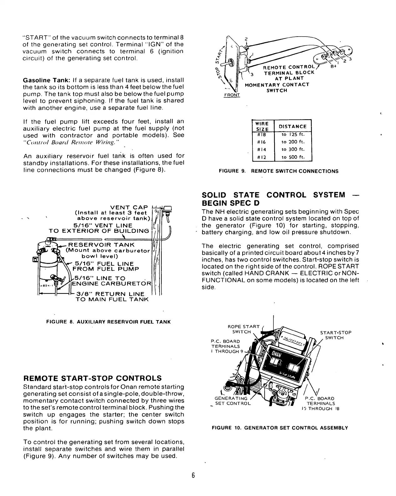
FRONT
REMOTE CONTROL,
TERMINAL BLOCK
AT PLANT
MOMENTARY CONTACT
SWITCH
WIRE
SIZE
DISTANCE
#18
to
125
ft.
#16
to
200
ft.
#14
to
300
ft.
#12
to
500
ft.
FIGURE
9.
REMOTE SWITCH CONNECTIONS
VENT
CAP
(Install
at
least
3
feet
above reservoir tank)
5/16" VENT LINE
TO EXTERIOR
OF
BUILDING
\
"l-rV— RESERVOIR TANK
(Mount above carburetor
bowl level)
5/16" FUEL LINE
FROM FUEL PUMP
5/16" LINE
TO
ENGINE CARBURETOR
•-3/8"
RETURN LINE
TO MAIN FUEL TANK
SOLID
STATE
CONTROL
SYSTEM
—
BEGIN
SPEC
D
The
NH
electric generating sets beginning with Spec
D have
a
solid state control system located
on top
of
the generator (Figure
10) for
starting, stopping,
battery charging,
and low
oil
pressure shutdown.
The electric generating
set
control, comprised
basically
of
a
printed circuit board about4 inches
by
7
inches,
has
two
control switches. Start-stop switch
is
located
on the
right side
of
the
control. ROPE START
switch (called HAND CRANK
—
ELECTRIC orNON-
FUNCTIONAL
on
some models)
is
located
on the
left
side.
FIGURE
8.
AUXILIARY RESERVOIR FUEL TANK
REMOTE
START-STOP
CONTROLS
Standard start-stop controls
for
Onan remote starting
generating
set
consist
of
asingle-pole, double-throw,
momentary contact switch connected
by
three wires
to
the
set's remote control terminal block. Pushing
the
switch
up
engages
the
starter;
the
center switch
position
is for
running; pushing switch down stops
the plant.
To control
the
generating
set
from several locations,
install separate switches
and
wire them
in
parallel
(Figure
9).
Any
number
of
switches
may
be
used.
ROPE
START
SWITCH
P.C.
BOARD
TERMINALS
I
THROUGH 9
START-STOP
SWITCH
c
GENERATING
SET CONTROL
P.C. BOARD
TERMINALS
10 THROUGH
18
FIGURE
10.
GENERATOR
SET
CONTROL ASSEMBLY
 Loading...


