The start-stop switch is pressed to START until the
generator set starts. The switch is pressed to STOP
until the generator set stops. Models with switch
indicated as ROPE START or HAND CRANK —
ELECTRIC, use the switch for manual rope starting
(models with rope sheave). Terminals
1
through 9 on
the left side of the control connect to the following
components:
a. Ignition Points — 6
b. Ignition Coil — 6
c. Start Solenoid — 9
d.
Low Oil Pressure Shutdown — 4
e. Choke — 2
f. Battery Charging Resistors — 7 and 8
Terminals 10 through 18 on the right side are for
control connections of a remote control station
including:
a. DC Voltmeter — 13 and 15
b. DC Battery Charging Ammeter — 17 and 18
c. Running Time Meter — 10 and 13
d.
Generator "ON" Light — 10 and 15
LOAD
WIRE CONNECTIONS
The generating set nameplate shows the electrical
output rating of the set in watts, volts and hertz. The
contractor and portable models are prewired and
have a receptacle box with two duplex 120-volt (15
ampere) grounding receptacles and two 240-volt (20
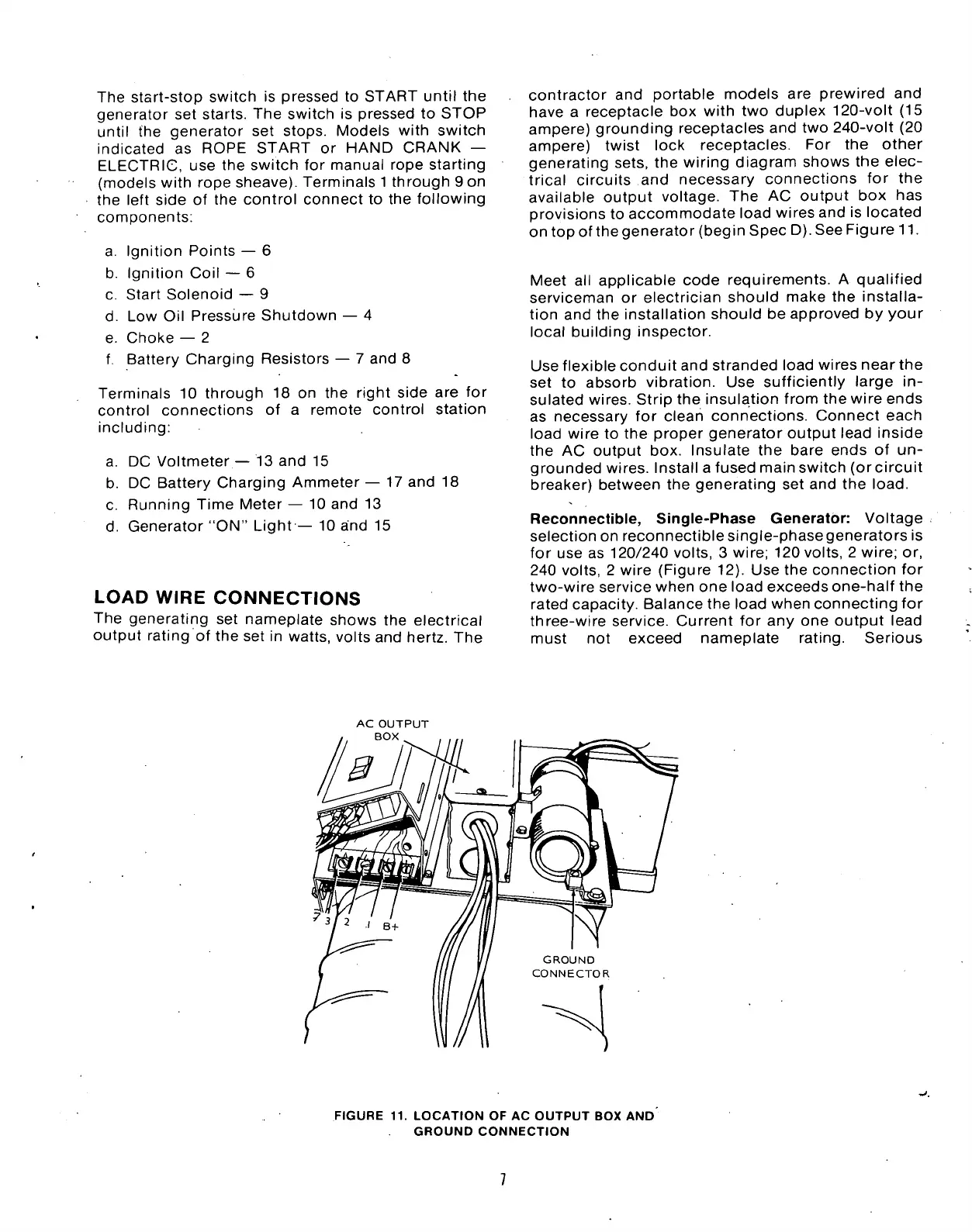
ampere) twist lock receptacles. For the other
generating sets, the wiring diagram shows the elec-
trical circuits and necessary connections for the
available output voltage. The AC output box has
provisions to accommodate load wires and is located
on top of the generator (begin Spec D). See Figure 11.
Meet all applicable code requirements. A qualified
serviceman or electrician should make the installa-
tion and the installation should be approved by your
local building inspector.
Use flexible conduit and stranded load wires near the
set to absorb vibration. Use sufficiently large in-
sulated wires. Strip the insulation from the wire ends
as necessary for clean connections. Connect each
load wire to the proper generator output lead inside
the AC output box. Insulate the bare ends of un-
grounded wires. Install a fused main switch (orcircuit
breaker) between the generating set and the
load.
Reconnectible, Single-Phase Generator: Voltage
selection on reconnectible single-phase generators is
for use as 120/240 volts, 3 wire; 120 volts, 2 wire; or,
240 volts, 2 wire (Figure 12). Use the connection for
two-wire service when one load exceeds one-half the
rated capacity. Balance the load when connecting for
three-wire service. Current for any one output lead
must not exceed nameplate rating. Serious
AC OUTPUT
BOX
FIGURE 11. LOCATION OF AC OUTPUT BOX AND
GROUND CONNECTION
 Loading...


