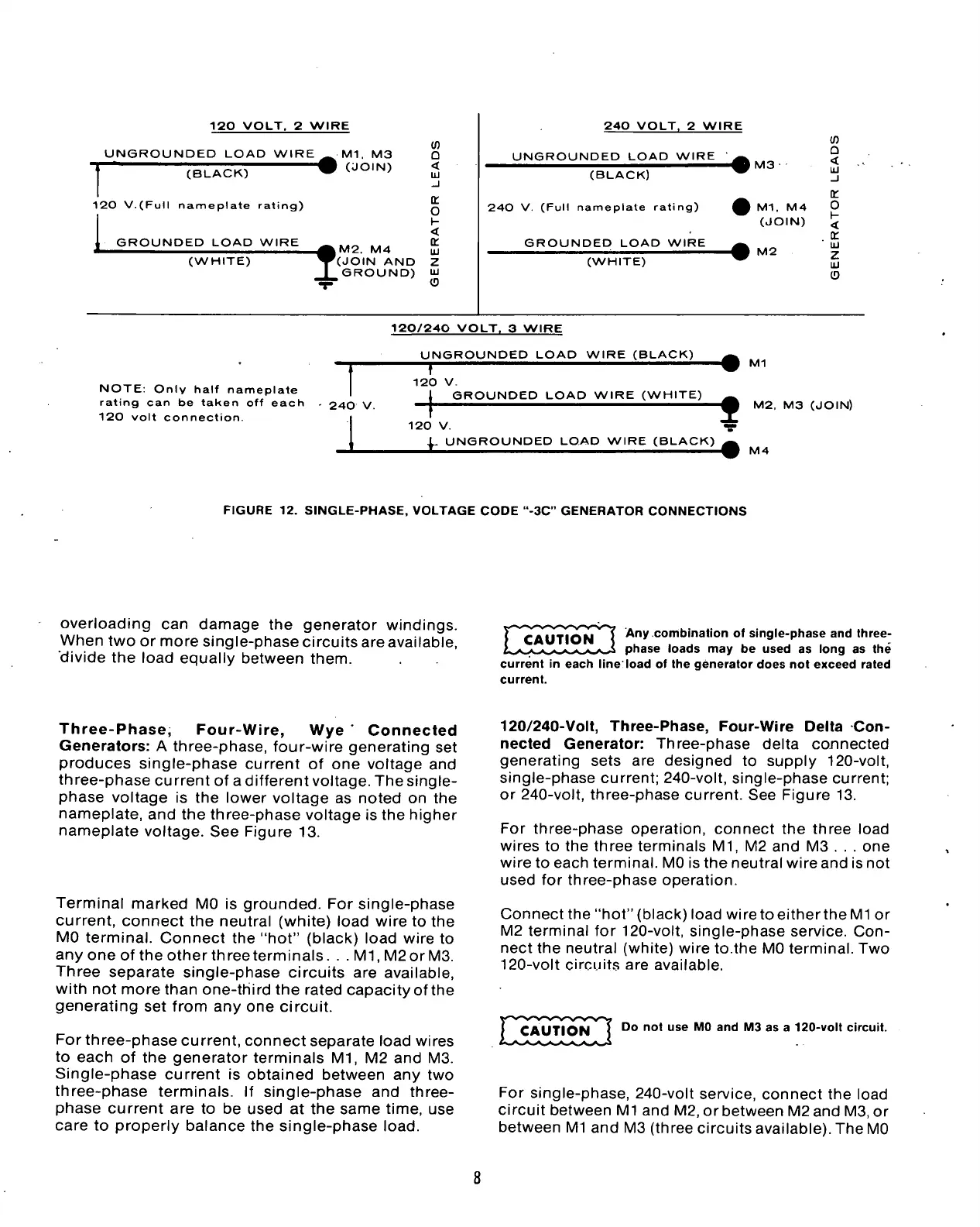
120 VOLT.
2
WIRE
UNGROUNDED LOAD WIRE
(BLACK)
120 V.(Full nameplate rating)
GROUNDED LOAD WIRE
Ml.
M3
I (JOIN)
(WHITE)
(!)
O
<
UJ
_l
Q:
o
\-
<
|M2.
M4 25
'(JOIN
AND Z
GROUND)
UJ
r (D
240 VOLT,
2
WIRE
UNGROUNDED LOAD WIRE
^
(BLACK)
240
V.
(Full nameplate rating)
£
GROUNDED LOAD WIRE
^
(WHITE)
^
I
M3
M1.
M4
(JOIN)
M2
tn
a
<
u
_l
OL.
0
H
<
CC
UJ
Z
UJ
O
120/240 VOLT.
3
WIRE
UNGROUNDED LOAD WIRE (BLACK)
NOTE:
Only half nameplate
rating
can be
taken
off
each
. 240 V.
120 volt connection.
T
120 V.
Ml
GROUNDED LOAD WIRE (WHITE)
t
M2,
M3
(JOIN)
120 V.
1.
UNGROUNDED LOAD WIRE (BLACK)
^
£ m M4
FIGURE
12.
SINGLE-PHASE, VOLTAGE CODE "-3C" GENERATOR CONNECTIONS
overloading
can
damage
the
generator windings.
When two
or
more single-phase circuits are available,
divide
the
load equally between them.
Any combination of single-phase and three-
phase loads may be used as long as the
current in each line'load of the generator does not exceed rated
current.
Three-Phase, Four-Wire,
Wye '
Connected
Generators:
A
three-phase, four-wire generating
set
produces single-phase current
of one
voltage
and
three-phase current
of
a different voltage. The single-
phase voltage
is the
lower voltage
as
noted
on the
nameplate,
and the
three-phase voltage
is
the higher
nameplate voltage.
See
Figure
13.
Terminal marked
MO is
grounded.
For
single-phase
current, connect
the
neutral (white) load wire
to the
MO terminal. Connect
the
"hot" (black) load wire
to
any one
of
the other three terminals.
.
.M1,M2orM3.
Three separate single-phase circuits
are
available,
with
not
more than one-third
the
rated capacity of the
generating
set
from
any one
circuit.
For three-phase current, connect separate load wires
to each
of the
generator terminals
Ml, M2 and M3.
Single-phase current
is
obtained between
any two
three-phase terminals.
If
single-phase
and
three-
phase current
are to be
used
at the
same time,
use
care
to
properly balance
the
single-phase
load.
120/240-Volt, Three-Phase, Four-Wire Delta
Con-
nected Generator: Three-phase delta connected
generating sets
are
designed
to
supply 120-volt,
single-phase current; 240-volt, single-phase current;
or 240-volt, three-phase current.
See
Figure
13.
For three-phase operation, connect
the
three load
wires
to the
three terminals
Ml, M2 and M3 . . . one
wire
to
each terminal. MO
is
the neutral wire and is not
used
for
three-phase operation.
Connect the "hot" (black) load wire to either the
Ml or
M2 terminal
for
120-volt, single-phase service.
Con-
nect
the
neutral (white) wire to.the MO terminal. Two
120-volt circuits
are
available.
CAUTION
Do not use MO and M3 as a 120-volt circuit.
For single-phase, 240-volt service, connect
the
load
circuit between
Ml
and M2,
or
between M2and M3,
or
between
Ml
and M3 (three circuits available). The MO
 Loading...


