DELTA GENERATOR CONNECTIONS
FOR
VOLTAGE CODE
-SD
UNGROUNDED LOAD WIRE
240
V.,
3 PHASE
-240 V..
•
—r~
240
V..
—H
240
v.;
L.
(BLACK)
UNGROUNDED
LOAD WIRE
(BLACK)
UNGROUNDED
LOAD WIRE
(BLACK)
|20V..
GROUNDED
LOAD
WIRsj
120
V..
_l_
(WHITE)
Ml
M2
I
M3
I
M0
WYE GENERATOR CONNECTIONS
FOR
VOLTAGE CODES
-4
AND
-4X
UNGROUNDED LOAD WIRE
3-PHASE
HIGHER
NAMEPLATE'
VOLTAGE
(BLACK)
UNGROUNDED LOAD WIRE
(BLACK)
| UNGROUNDED LOAD WIRE
(BLACK)
T
GROUNDED LOAD WIRE
llj
|
Ml
)M2
|M3
IMO
(WHITE)
A
-
Lower nameplate voltage,
I
phase circuit.
B
-
Higher nameplate voltage,
I
phase circuit.
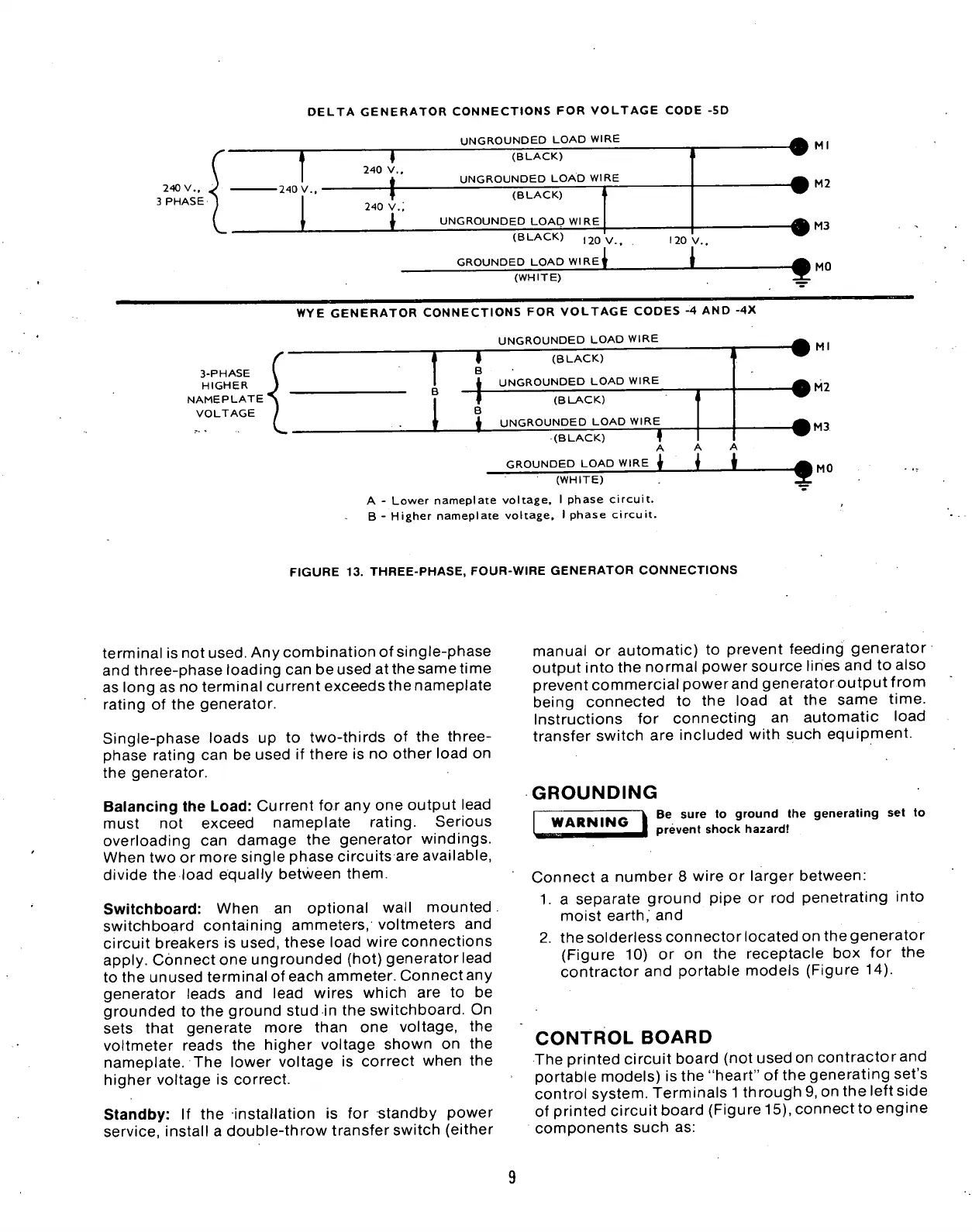
FIGURE
13.
THREE-PHASE, FOUR-WIRE GENERATOR CONNECTIONS
terminal
is
not used. Any combination
of
single-phase
and three-phase loading can be used atthesametime
as long
as no
terminal current exceeds the nameplate
rating
of
the
generator.
Single-phase loads
up to
two-thirds
of
the
three-
phase rating
can be
used
if
there
is no
other load
on
the generator.
Balancing
the
Load: Current
for
any one output lead
must
not
exceed nameplate rating. Serious
overloading
can
damage
the
generator windings.
When two
or
more single phase circuits are available,
divide
the
load equally between them.
Switchboard: When
an
optional wall mounted
switchboard containing ammeters, voltmeters
and
circuit breakers
is
used, these load wire connections
apply. Connect one ungrounded (hot) generator lead
to the unused terminal
of
each ammeter. Connect any
generator leads
and
lead wires which
are
to be
grounded
to the
ground stud
in the
switchboard.
On
sets that generate more than
one
voltage,
the
voltmeter reads
the
higher voltage shown
on the
nameplate.
The
lower voltage
is
correct when
the
higher voltage
is
correct.
Standby:
If
the
installation
is for
standby power
service, install
a
double-throw transfer switch (either
manual
or
automatic)
to
prevent feeding generator
output into the normal power source lines and
to
also
prevent commercial powerand generatoroutputfrom
being connected
to the
load
at the
same time.
Instructions
for
connecting
an
automatic load
transfer switch
are
included with such equipment.
GROUNDING
WARNING
Be sure
to
ground
the
generating
set to
prevent shock hazard!
Connect
a
number
8
wire
or
larger between:
1.
a
separate ground pipe
or
rod
penetrating into
moist earth,
and
2.
the solderless connector located on the generator
(Figure
10)
or on the
receptacle
box
for
the
contractor
and
portable models (Figure
14).
CONTROL
BOARD
The printed circuit board (not used on contractorand
portable models)
is
the "heart"
of
the generating set's
control system. Terminals
1
through 9, on the left side
of printed circuit board (Figure 15), connectto engine
components such
as:
 Loading...


