GROUND
CONNECTOR
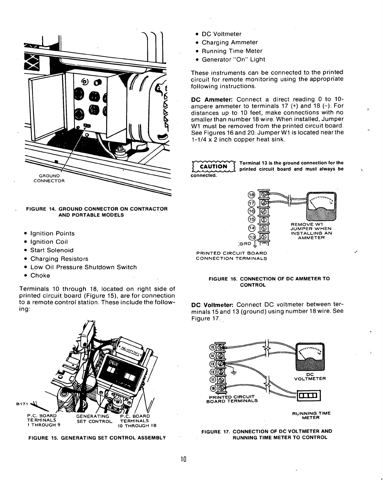
FIGURE 14. GROUND CONNECTOR ON CONTRACTOR
AND PORTABLE MODELS
• Ignition Points
• Ignition Coil
• Start Solenoid
• Charging Resistors
• Low Oil Pressure Shutdown Switch
• Choke
Terminals 10 through 18, located on right side of
printed circuit board (Figure 15), are for connection
to a remote control station. These include the follow-
ing:
3171 "^^^
P.C BOARD
TERMINALS
I THROUGH 9
GENERATING
SET CONTROL
P.C. BOARD
TERMINALS
10 THROUGH 18
• DC Voltmeter
• Charging Ammeter
• Running Time Meter
• Generator "On" Light
These instruments can be connected to the printed
circuit for remote monitoring using the appropriate
following instructions.
DC Ammeter: Connect a direct reading 0 to 10-
ampere ammeter to terminals 17 (+) and 18 (-). For
distances up to 10 feet, make connections with no
smaller than number 18 wire. When installed, Jumper
Wl must be removed from the printed circuit board.
See Figures 16and 20. JumperWI is located nearthe
1-1/4 x 2 inch copper heat sink.
CAUTION
Terminal 13 is the ground connection for the
printed circuit board and must always be
connected.
RD £
REMOVE Wl
JUMPER WHEN
INSTALLING AN
AMMETER
;e
PRINTED CIRCUIT BOARD
CONNECTION TERMINALS
FIGURE 16. CONNECTION OF DC AMMETER TO
CONTROL
DC Voltmeter: Connect DC voltmeter between ter-
minals 15 and 13 (ground) using number 18 wire. See
Figure 17.
PRINTED CIRCUIT
BOARD TERMINALS
RUNNING TIME
METER
FIGURE 15. GENERATING SET CONTROL ASSEMBLY
FIGURE 17. CONNECTION OF DC VOLTMETER AND
RUNNING TIME METER TO CONTROL
10
 Loading...


