-
-
DIODE IN4004
(p)
24 V.
LAMP
15
10
-
-
DIODE IN4004
(£)l2
V.
LAMP
ZENER DIODE
6 VOLT, 5WATT
IN 5340
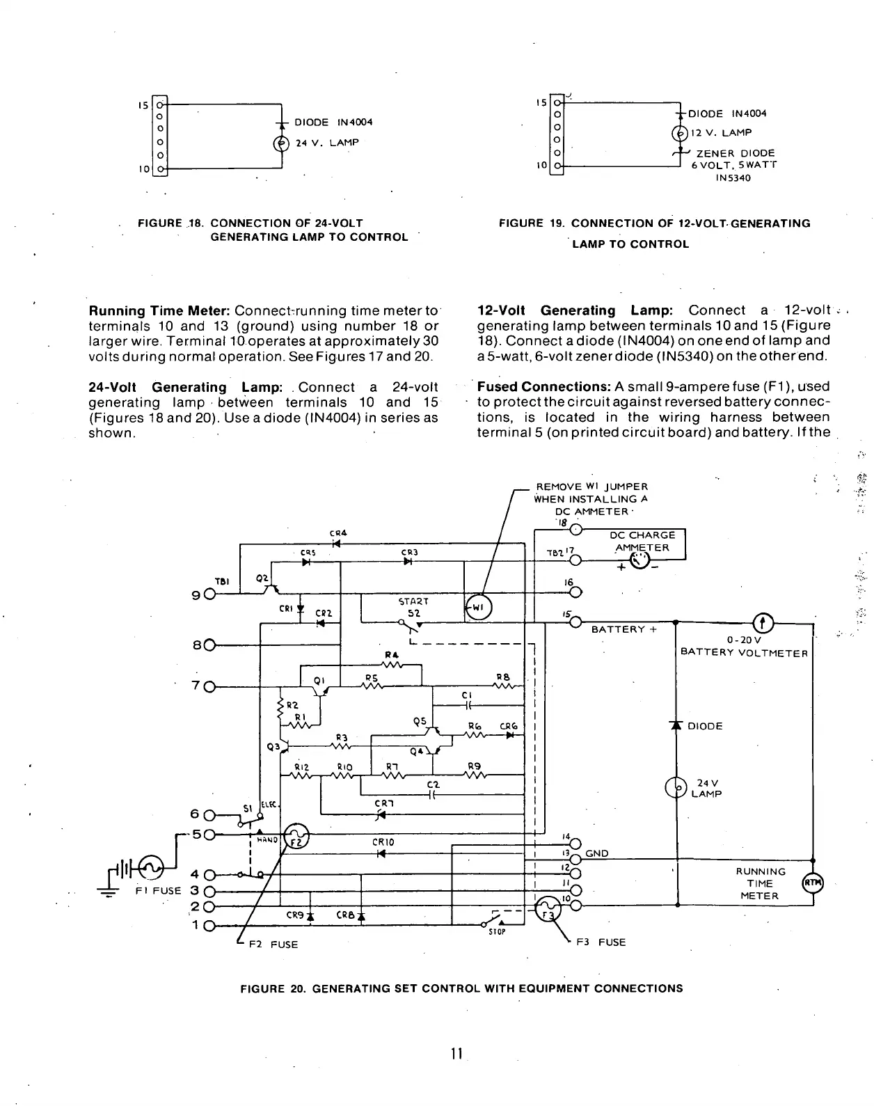
FIGURE
.18.
CONNECTION
OF
24-VOLT
GENERATING LAMP
TO
CONTROL
FIGURE
19.
CONNECTION
OF
12-VOLT GENERATING
LAMP
TO
CONTROL
Running Time Meter: Connect-running time meter
to
terminals
10 and 13
(ground) using number
18 or
larger wire. Terminal lO operates
at
approximately 30
volts during normal operation. See Figures 17 and 20.
24-Volt Generating Lamp:
.
Connect
a
24-volt
generating lamp between terminals
10 and 15
(Figures 18 and 20). Use a diode (IN4004)
in
series
as
shown.
12-Volt Generating Lamp: Connect
a
12-volt
generating lamp between terminals lOand 15 (Figure
18).
Connect a diode (IN4004) on one end
of
lamp and
a5-watt, 6-voltzenerdiode (IN5340) on theotherend.
Fused Connections:
A
small 9-ampere fuse (Fl), used
to protect the circuit against reversed battery connec-
tions,
is
located
in the
wiring harness between
terminal
5
(on printed circuitboard) and battery. Ifthe
REMOVE Wl JUMPER
WHEN INSTALLING
A
DC AMMETER•
IS,
("50
-±-
Fl
FUSE 3 O
DC
CHARGE
AMMETER
BATTERY
+
0-20V
BATTERY
VOLTMETER
DIODE
24
V
LAMP
RUNNING
TIME
METER
F2 FUSE
F3 FUSE
FIGURE
20.
GENERATING
SET
CONTROL WITH EQUIPMENT CONNECTIONS
 Loading...


