fuse is damaged (caused by connecting the battery
backwards), replace with an SFE9 automotive type
fuse.
See Figure 20.
Terminal 5 has a PC fuse connection (F2) in the
battery lead to protect the printed circuit board from
any shorts on the board or from external remote
connections. Terminal 10 has a PC fuse connection
(F3) in the generator lead to protect the printed circuit
board from any external shorts when using the
remote connections. If F2 or F3 printed circuit board
path is "blown", replace either with number 22 wire,
one inch long and solder into circuit.
T^^^J^^J^
Do not attempt to check for current flow on
L^K^^^ys^J, the printed circuit board by jumpering across
components with a screwdriver, wire, etc. Always have these
boards checked by an authorized Onan Service Center or a
qualified electrician using the proper instruments
(e.g.,
voltmeter,
ohmmeter, or multimeter).
BATTERY
CONNECTION (Prior
Spec
D)
Connect battery positive (+) to the start solenoid
(located in the control box). Connect the battery
negative (-) to a good ground on thegeneratorframe.
Enter control box side to install battery cable (Figure
21).
CAUTIONJ
Do not disconnect starting batteries while the
set is running. The resulting overvoltage
condition will damage the electric choke and may damage control
components.
FIGURE 21. BATTERY CONNECTIONS (PRIOR SPEC D)
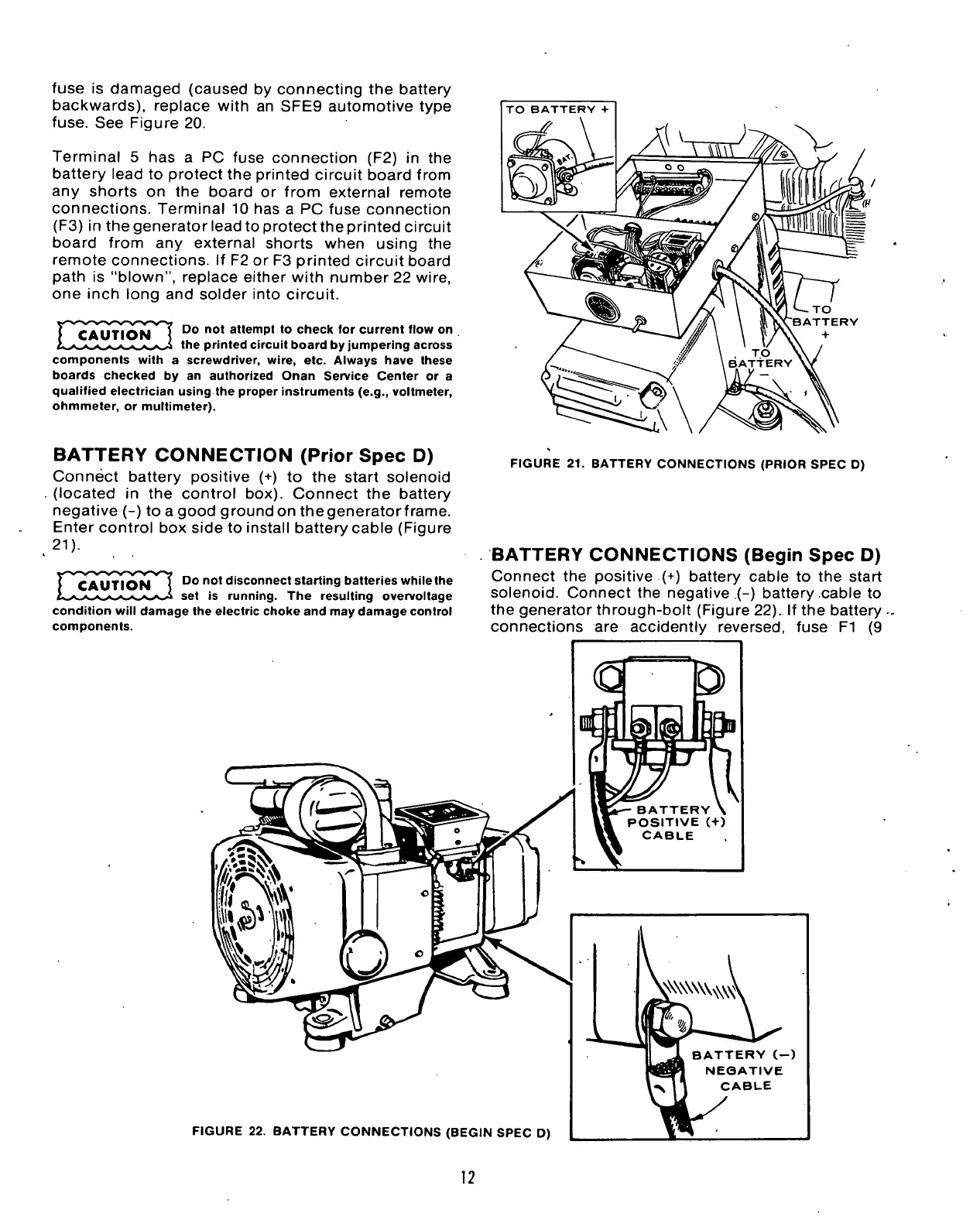
BATTERY
CONNECTIONS (Begin
Spec
D)
Connect the positive (+) battery cable to the start
solenoid.
Connect the negative .(-) battery cable to
the generator through-bolt (Figure 22). If the battery .
connections are accidently reversed, fuse Fl (9
FIGURE 22. BATTERY CONNECTIONS (BEGIN SPEC D)
BATTERY (-)
NEQATIVE
-V 1 1 CABLE
12
 Loading...


