TABLE
1.
TIMING
BUlTONS
16orS
15
or
R
14orP
13
or
N
12orM
GROUP
1
I
GROUP
2
I
CODE
I
PARTNO.
I
SI
147-0186
147-0187
147-0188
147-0189
147-0190
I
I
I
Inch
~~
-134
.131
-128
.125
.122
I
CODE
I
PARTNO.
I
S
mm
147-0161
Button
12
or
Y
is
the mid-range
of
the button sizes used the most.
The button dimension is determined by the number or letter
stamped on its side, Figure
25.
BUTTON WITH CODE LETTER
OR
NUMBER STAMPED ON
IT.
FIGURE
25.
TAPPET BUTTON CODE
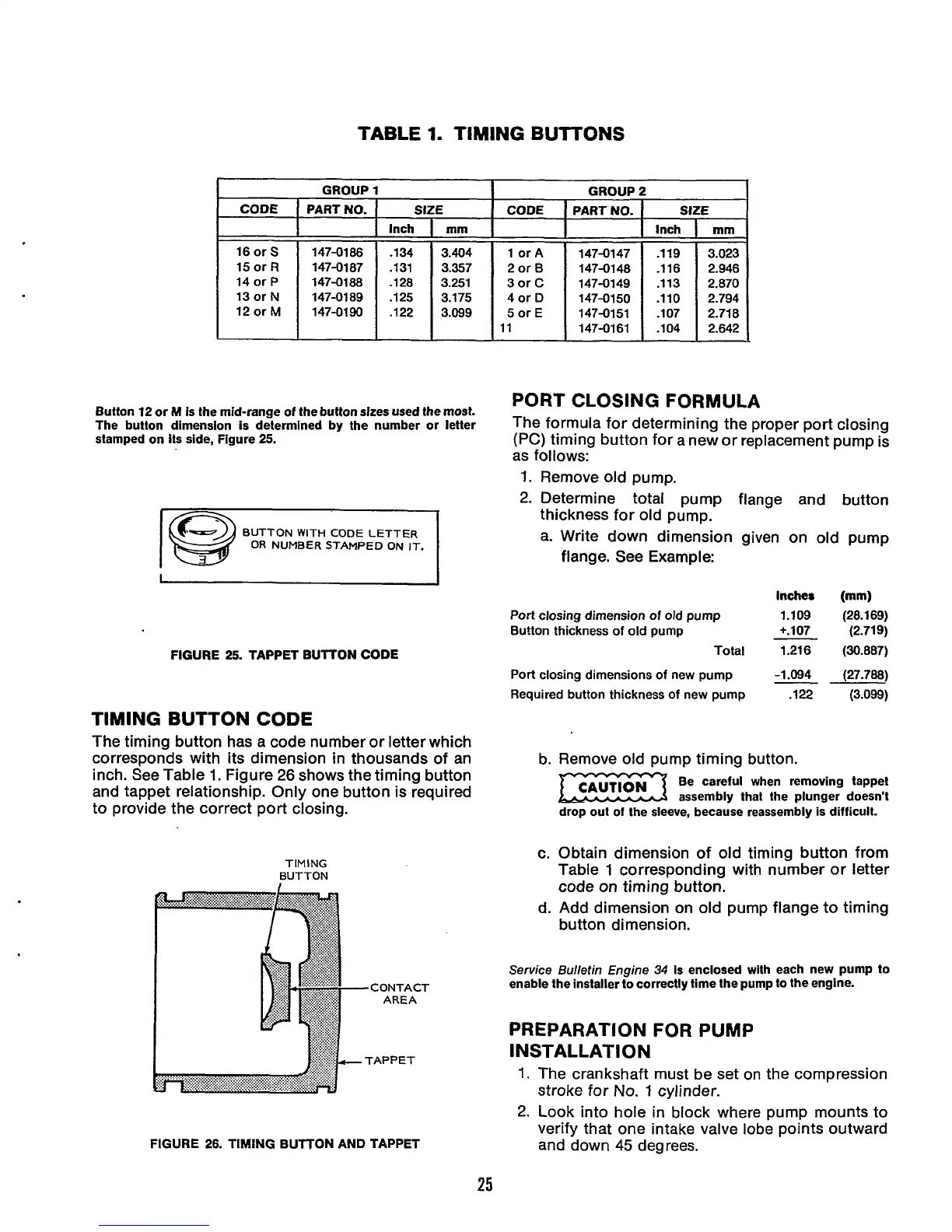
TIMING BUTTON
CODE
The timing button has a code number or letter which
corresponds with its dimension in thousands of an
inch. See Table
1.
Figure
26
shows the timing button
and tappet relationship. Only one button is required
to provide the correct port closing.
TIMING
BUTTON
FIGURE
26.
TIMING BUTTON AND TAPPET
3.023
2.946
2.870
2.794
2.718
2.642
PORT CLOSING FORMULA
The formula for determining the proper port closing
(PC) timing button for a new or replacement pump is
as follows:
1.
Remove old pump.
2.
Determine total pump flange and button
thickness for old pump.
a. Write down dimension given on old pump
flange. See Example:
Inches (mm)
Port
closing dimension
of
old pump
1.109 (28.169)
Bu!ton thickness
of
old pump
+.lo7 (2.719)
Total
1.216 (30.887)
Port
closing dimensions
of
new pump
-1.094 (27.788)
Required button thickness
of
new pump
.122 (3.099)
b. Remove old pump timing button.
Be careful when removing tappet
assembly that the plunger doesn't
drop out of the sleeve, because reassembly is difficult.
c. Obtain dimension of old timing button from
Table
1
corresponding with number or letter
code on timing button.
d. Add dimension on old pump flange to timing
button dimension.
Service Bulletin Engine
34
Is enclosed with each new pump to
enable the installer to correctly time the pump to the engine.
PREPARATION
FOR
PUMP
INSTALLATI ON
1.
The crankshaft must be set on the compression
stroke
for
No.
1
cylinder.
2.
Look into hole in block where pump mounts to
verify that one intake valve lobe points outward
and down
45
degrees.
25
 Loading...
