FLYWHEEL
The flywheel is a tapered fit on the crankshaft.
Improvise a puller, using at least a 7/16-inch bar
(11.113 mm), and drill two 7/16-inch (11.113 mm)
holes 2-7/8 inches (73.025 mm) between centers.
Loosen the flywheel mounting screw a few turns.
Place bar against the flywheel screw and attach bar,
using two 3/8-16 thread screws
in
the holes provided
in flywheel. Alternately tighten the screws until
flywheel is free.
FLYWHEEL REPLACEMENT
Replacement flywheels are supplied without the
timing markings because each flywheel must befitted
to
its engine. The only accurate method of determing
the top dead center (TDC) and port closing points is
to
measure the piston travel. This is a critical
measurement and should be attempted only with
accurate, dependable equipment.
With the flywheel mounted, remove the head and
install a depth gauge over the front piston. Rotate the
flywheel to find the TDC position on the compression
stroke and mark this point on the flywheel. Next, turn
the flywheel counterclockwise
until
the piston drops
exactly 0.128 inch (3.25 mm). Mark both TDC and
piston drop to PC point on the flywheel.
Ring
Gear:
To
remove the ring gear, if damaged, saw
part way through, then break it using acold chisel and
heavy hammer.
To
install a new ring gear, place
it
in
an oven heated to
380"
F
-
400"
F
(192"
to 204"
C)
for 30 to 40 minutes.
Do
not heat with a torch or ring gear may be
warped.
When heated properly, the ring will fall into place on
the flywheel. If it does not go on all the way by itself,
drive
it
into place with a hammer.
Do
itfastand do not
damage the gear teeth. The ring will contract rapidly
and may shrink to the flywheel before
it
is
in
place. If
this occurs, a new ring gear may be required.
GEAR
COVER
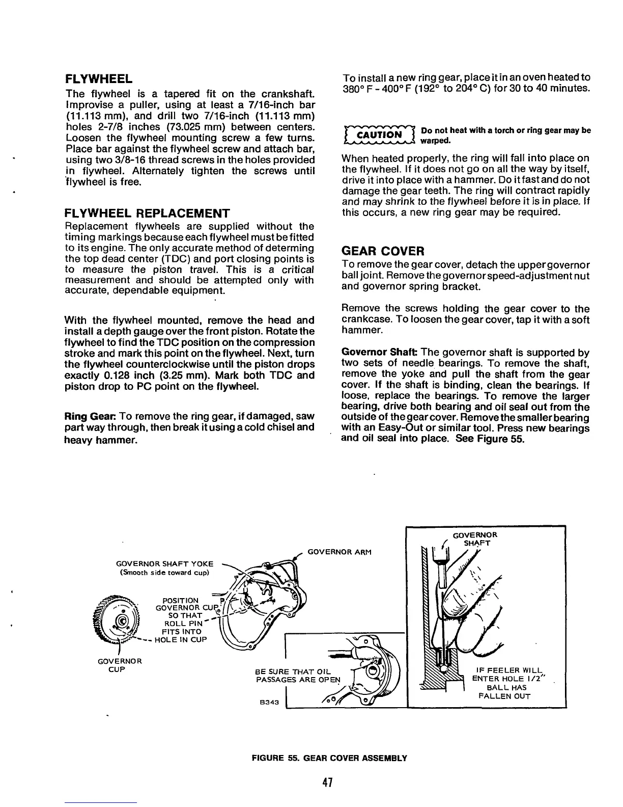
To remove the gear cover, detach the uppergovernor
ball joint. Remove thegovernorspeed-adjustment nut
and governor spring bracket.
Remove the screws holding the gear cover to the
crankcase. To loosen the gear cover, tap
it
with a soft
hammer.
Governor
Shaft
The governor shaft is supported by
two sets of needle bearings.
To
remove the shaft,
remove the yoke and pull the shaft from the gear
cover. If the shaft is binding, clean the bearings. If
loose, replace the bearings. To remove the larger
bearing, drive both bearing and oil seal out from the
outside
of
the gear cover. Remove the smaller bearing
with an Easy-Out
or
similar tool. Press new bearings
and oil seal into place. See Figure
55.
GOVERNOR
GOVERNOR ARM
.
GOVERNOR SHAFT
YOKE
(Smooth
side
toward
cup)
FITS
INTO
GOVERNOR
CUP BE
SURE
THAT
OIL
PASSAGES ARE OPEN
I
8343
IF
FEELER
WILL
ENTER HOLE
112"
,
BALL HAS
FALLEN OUT
FIGURE
55.
GEAR
COVER
ASSEMBLY
47
 Loading...
