Gear Cover Oil Seal:
Replace the oil seal if damaged
or worn. Drive the oil seal out from inside the gear
cover. Lay the cover on a board
so
the seal boss is
supported. Using an oil seal driver, insertthe new seal
from the inside with rubber lip toward outside of gear
cover (open side of seal inward) and drive it flush with
the outside surface. During gear cover installation,
use the driver to protect the oil seal. See Figure 56.
Assembly, Gear Cover:
1. Work governor shaft to check for binding and see
that the governor shaft end-thrust ball is
in
place,
Figure 55.
2. Turn governor yoke
so
smooth side is toward
governor cup.
3.
Turn gove,rnor cup
so
stop pin in gear cover will fit
into one of the holes in the cup surface (Figure
55). Measure distance from end of stop pin to
mounting face of cover. It should be 25/32 inch
(19.844
mm). If it isnot, replace pin. Pin should be
positioned with open end facing crankshaft seal.
4. Coat oil seal lip with oil or grease. Set a piece of
shim stock over the crankshaft keyway to protect
seal and install gear cover. Tighten mounting
screws
to
15 to 20 foot-pounds (20 to 27 Nom).
Before tightening screws, be sure the stop pin is
in governor hole.
GEAR COVER
INSTALL OIL SEAL
FLUSH WITH THIS
SURFACE
'1
FOILSEAL
.. ,...
THIS SURFACE MUST
'.::$>
k..fl
BE CLEAN BEFORE
INSTALLING
SEAL
'
FIGURE
56.
GEAR COVER
OIL
SEAL
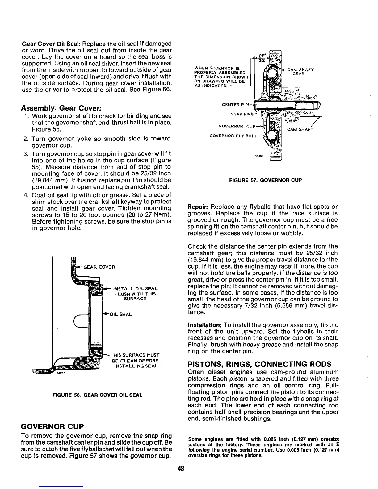
GOVERNOR
CUP
To
remove the governor cup, remove the snap ring
from the camshaft center
pin
and slide the cupoff. Be
sure to catch the five flyballs that will fall out when the
cup is removed. Figure
57
shows the governor cup.
WHEN GOVERNOR
IS
CAM
SHAFT
CENTER PIN
GOVERNOR CUP
GOVERNOR FLY
BAL
FIGURE
57.
GOVERNOR CUP
Repair:
Replace any flyballs that have flat spots or
grooves. Replace the cup if the race surface is
grooved or rough. The governor cup must be a free
spinning fit on the camshaft center pin, but should be
replaced if excessively loose or wobbly.
Check the distance the center pin extends from the
camshaft gear; this distance must be 25/32 inch
(19.844 mm) to give the propertravel distance for the
cup.
If
it is less, the engine may race; if more, the cup
will not hold the balls properly. If the distance is too
great, drive or press the center pin in. If it is too small,
replace the pin; it cannot be removed withoutdamag-
ing the surface. In some cases, if the distance is too
small, the head of the governor cup can be ground to
give the necessary 7/32 inch (5.556 mm) travel dis-
tance.
Installation:
To
install the governor assembly, tip the
front of the unit upward. Set the flyballs in their
recesses and position the governor cup on its shaft.
Finally, brush with heavy grease and install the snap
ring on the center pin.
PISTONS,
RINGS,
CONNECTING RODS
Onan diesel engines use cam-ground aluminum
pistons. Each piston is tapered and fitted with three
compression rings and an oil control ring. Full-
floating piston pins connect the piston to its connec-
ting rod. The pins are held
in
place with a snap ring at
each end. The lower end of each connecting rod
contains half-shell precision bearings and the upper
end
,
semi -f
i
n
ish ed bushings.
Some engines are fitted with 0.005 inch (0.127 mm) oversize
plstons
at
the factory. These engines are marked with an E
following the engine serial number. Use 0.005 inch (0.127 mm)
oversize rings for these pistons.
48
 Loading...
