'
Removal and Disassembly
On 2-cylinder engines, the connecting rod and cap
are stamped for installation
in
the proper cylinder.
When removing piston assemblies, check the mark-
ing
so
each can be installed in the proper cylinder.
1.
Drain crankcase oil and remove oil base.
2. Remove cylinder heads.
3.
Before pushing pistons out, scrape carbon at top
,
of cylinder bore.
4. Remove cap from each connecting rod and push
assembly through top of cylinder bore. Replace
cap and bearing inserts in proper assembly.
5.
Using a ring expander, remove rings from each
pis ton.
6. Remove two retaining rings and push piston pin
from each piston.
Cylinders
The cylinder walls should be free of scratches, pitting
and scuffing. Check each with an inside reading
micrometer for out-of-round and wear. The bore
should measure between
3.4995
inches
(88.8873
mm)
and
3.5005
inches
(88.9127
mm) and be less than
0.001
inch
(0.0243
mm) out-of-round.
If necessary, rebore the cylinder
to
fit the next
available oversize piston. Pistons and rings are
available in
0.005
inch
(0.127
mm),
0.010
inch
(2.540
mm),
0.020
inch
(0.508
mm)
0.030
inch
(0.762
mm) and
0.040
inch
(1.016
mm) oversize. If the
cylinders do not need refinishing, remove any ex-
isting ridges from the top of the walls with a finestone.
Pistons:
Clean thoroughly and inspect each piston. Clean the
carbon from the ring grooves and besure all oil holes
are open.
If
any piston
is
badly scored or burred, loose
in the cylinder, has badly worn ring grooves or
otherwise
is
not in good condition, replace it. See
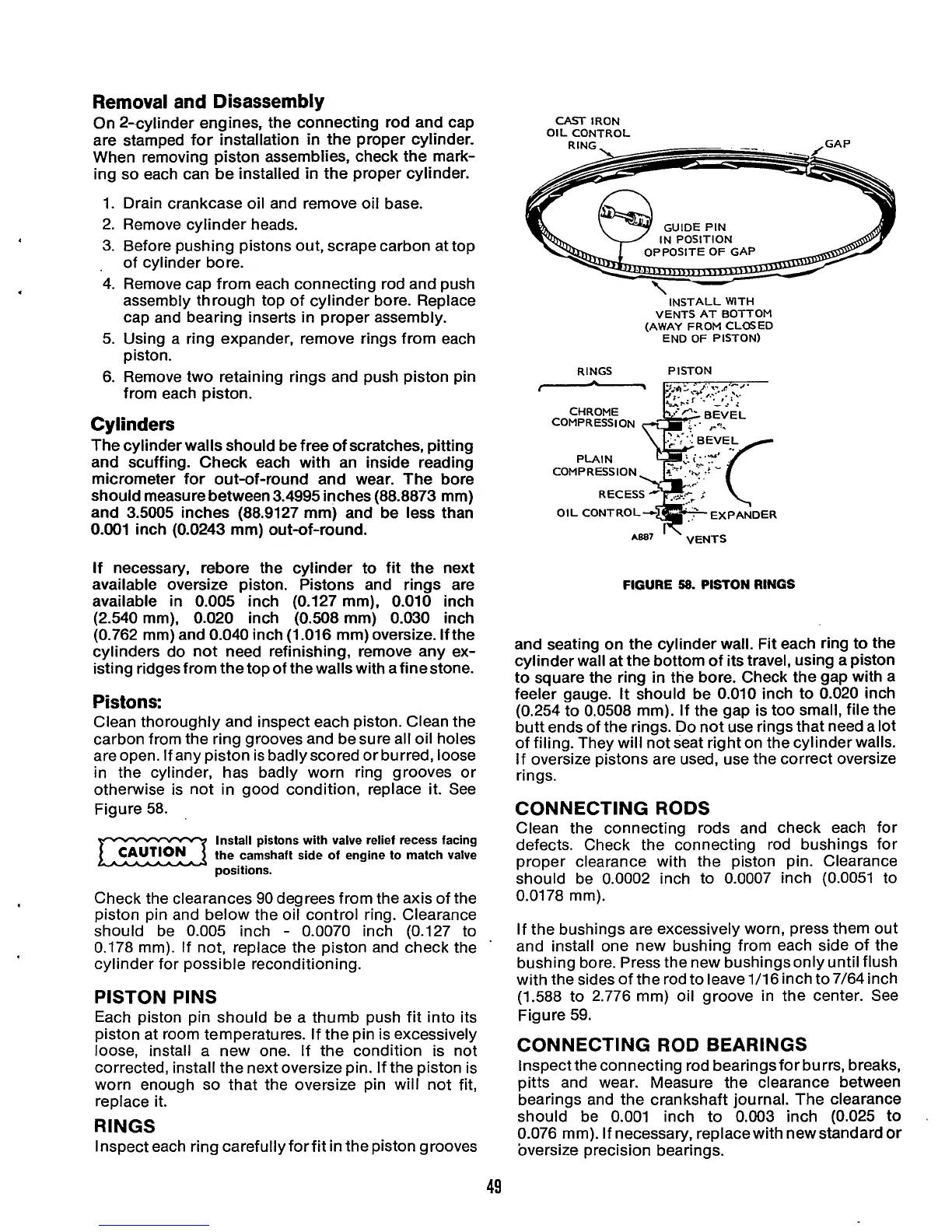
Figure 58.
m
positions.
Check the clearances
90
degrees from the axis of the
piston pin and below the oil control ring. Clearance
should be
0.005
inch
-
0.0070 inch (0.127 to
0.178 mm).
If
not, replace the piston and check the
'
cylinder for possible reconditioning.
PISTON PINS
Each piston pin should be a thumb push fit into its
piston at room temperatures. If the pin is excessively
loose, install a new one. If the condition is not
corrected, install the next oversize pin. If the piston is
worn enough
so
that the oversize pin will not fit,
replace it.
RINGS
Inspect each ring carefullyforfit in the piston grooves
Install pistons with valve relief recess facing
the camshaft side of engine
to
match valve
CAUTION
~
.-
IN
POSITION
CAST
IRON
OIL CONTROL
INSTALL WlTH
VENTS AT BOTTOM
(AWAY
FROM
CLOSED
END
OF
PISTON)
RINGS PISTON
CHROME BEVEL
COMPRESSION
RECESS
-1
AB87
'
'
VENTS
FIGURE
58.
PISTON
RINGS
and seating on the cylinder wall. Fit each ring
to
the
cylinder wall at the bottom of its travel, using a piston
to square the ring
in
the bore. Check the gap with a
feeler gauge.
It
should be
0.010
inch to
0.020
inch
(0.254 to 0.0508 mm).
If
the gap is too small, file the
butt ends of the rings. Do not use rings that need a lot
of filing. They will not seat right on the cylinder walls.
If
oversize pistons are used, use the correct oversize
rings.
CONNECTING
RODS
Clean the connecting rods and check each for
defects. Check the connecting rod bushings for
proper clearance with the piston pin. Clearance
should be 0.0002 inch to 0.0007 inch
(0.0051
to
0.0178 mm).
If
the bushings are excessively worn, press them out
and install one new bushing from each side of the
bushing bore. Press the new bushings only until flush
with the sides of the rod to leave 1/16 inch to 7/64 inch
(1.588 to 2.776 mm) oil groove in the center. See
Figure
59.
CONNECTING
ROD
BEARINGS
Inspect the connecting rod bearingsfor burrs, breaks,
pitts and wear. Measure the clearance between
bearings and the crankshaft journal. The clearance
should be
0.001
inch to
0.003
inch
(0.025
to
0.076 mm).
If
necessary, replace with new standard
or
oversize precision bearings.
49
 Loading...
