CONNECTING ROD
BUSHING ENDS
M
BE FLUSH WITH
S
OF
ROD TO PER
1/16”01L GROOVE
BETWEEN BUSHINGS
II
Iiil
F
’RECISION TYPE
BEARING
’
MEASURE CLEP
DIRECTION INDl
ARROW
A881
Rev.
rR
IC
LANCE
:ATED
3SS-S
ECTl ON
IN
BY
FIGURE
‘59.
CONNECTING
ROD
BUSHINGS
ASSEMBLY AND INSTALLATION
1.
2.
3.
4.
5.
6.
7.
8.
9.
Install connecting rods on each piston with pins
and retaining rings. If new bushings were in-
stalled, check to see that ends are flush with
connecting rod to provide for oil recess
in
center.
Install all
rings on each piston. Tapered-type
rings will be marked
top
or identified in some
other manner. Place this mark toward closed end
of piston. Space ring gaps
1/4
of way around
piston from one another.
No
gap should be in line
with the piston pin.
Position a bearing half
in
each connecting rod. Be
sure there is no dirt under bearing. This could
cause
high
spots and early bearing failure.
Oil cylinder walls. Install each piston in proper
cylinder using a suitable installer. Each assembly
should be installed with stamp on piston facing
same direction as when removed.
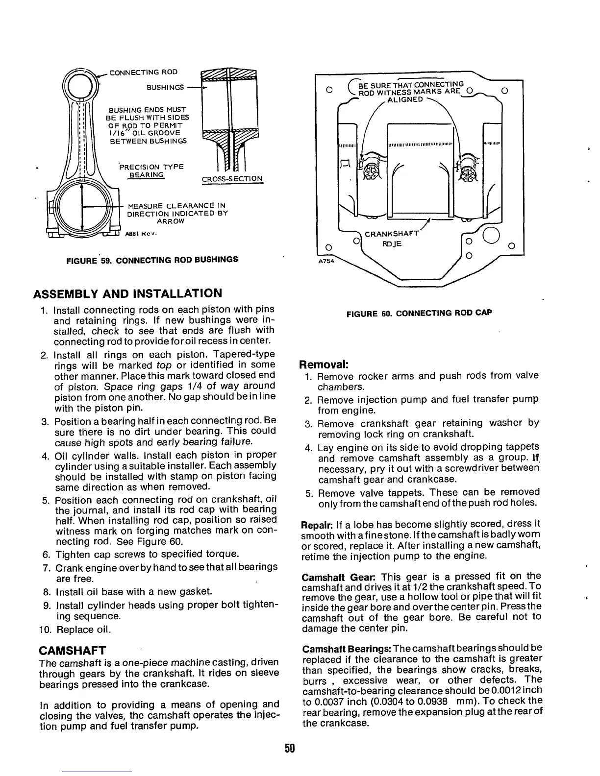
Position each connecting rod on crankshaft, oil
the journal, and install its rod cap with bearing
half. When installing rod cap, position
so
raised
witness mark on forging matches mark on con-
necting rod. See Figure
60.
Tighten cap screws to specified torque.
Crank engine over by hand to see that all bearings
are free.
Install oil base with a new gasket.
Install cylinder heads using proper bolt tighten-
ing sequence.
10.
Replace oil.
CAMSHAFT
The camshaft is a one-piece machine casting, driven
through gears by the crankshaft.
It
rides on sleeve
bearings pressed into the crankcase.
In
addition to providing
a
means of opening and
closing the valves, the camshaft operates the injec-
tion pump and fuel transfer pump.
FIGURE 60. CONNECTING
ROD
CAP
Removal:
1.
Remove rocker arms and push rods from valve
chambers.
2.
Remove injection pump and fuel transfer pump
from engine.
3.
Remove crankshaft gear retaining washer by
removing lock ring on crankshaft.
4. Lay engine on its side to avoid dropping tappets
and remove camshaft assembly as a group.
If.
necessary, pry it out with a screwdriver between
camshaft gear and crankcase.
5.
Remove valve tappets. These can be removed
only from the camshaft end of the push rod holes.
Repair:
If a lobe has become slightly scored, dress it
smooth with afinestone. If the camshaft is badly worn
or scored, replace it. After installing a new camshaft,
retime the injection pump to the engine.
Camshaft Gear:
This gear is a pressed fit on the
camshaft and drives it at
1/2
the crankshaft speed.To
remove the gear, use a hollow tool or pipe that will fit
inside the gear bore and over the center pin. Press the
camshaft out of the gear bore. Be careful not to
damage the center pin.
Camshaft Bearings:
Thecamshaft bearings should be
replaced if the clearance to the camshaft is greater
than specified, the bearings show cracks, breaks,
burrs
,
excessive wear, or other defects. The
camshaft-to-bearing clearance should be
0.001
2
inch
to
0.0037
inch (0.0304 to
0.0938
mm).
To
check the
rear bearing, remove the expansion plug at the rear of
the crankcase.
50
 Loading...
