Seite / Page 10
38629, Edition / Ausgabe 2012-05, Version 4
DeutschEnglish Abbildung / Figure
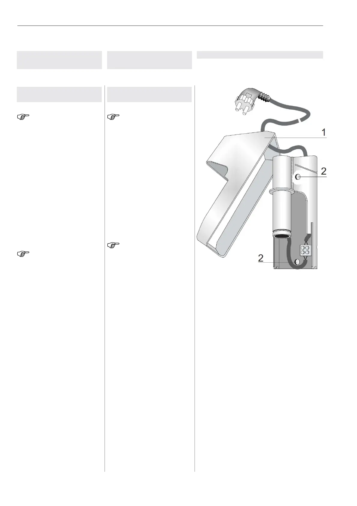
Figure / Abbildung 1
1 Plastic cover parts (here, part 2)
Kunststoffabdeckteile (hier Teil 2)
2 Holes for fastening agent
Bohrungen für Befestigungsmittel
3 Wall model
3.1 Installing the wall bea-
ring Fig.1
NOTE:
For the mains connection of the wall
model, it is necessary to have a pro-
perly grounded socket in the vicini-
ty of the connection cable.
1. Remove the two plastic co-
vers (1).
2. Make the vertical markings ac-
cording to the drilling templa-
te.
3. Drill two holes according to the
specifications of the manufac-
turer of the fastener.
4. Insert the fastener flush with
the wall.
NOTE:
Continue the installation only after
the binding agent has hardened com-
pletely.
5. Insert the fastener in the two
holes (2) and bolt the wall
bearing vertically to the wall.
6. Put on both the plastic covers
(1) and check them for secu-
re seating.
3 Wandausführung
3.1 Wandlager montieren
Abb. 1
HINWEIS:
Für den Netzanschluß des Wandge-
rätes ist eine ordnungsgemäß geer-
dete Steckdose im Bereich der An-
schlußleitung notwendig.
1. Zwei Kunststoffabdeckteile
(1) abnehmen.
2. Nach Bohrschablone senk-
recht anreißen.
3. Zwei Bohrungen nach Anga-
ben des Befestigungsmittel-
herstellers bohren.
4. Befestigungsmittel bündig mit
der Wand einsetzen.
HINWEIS:
Die Montage erst nach dem Aushär-
ten des Bindemittels fortsetzen.
5. Befestigungsmittel in die bei-
den Bohrungen (2) einstek-
ken und Wandlager senkrecht
anschrauben.
6. Die beiden Kunststoffab-
deckteile (1) aufsetzen und
sicheren Sitz prüfen.