Seite / Page 11
38629, Edition / Ausgabe 2012-05, Version 4
3 Wandausführung
3.2 Ausleger mit Federarm
montieren
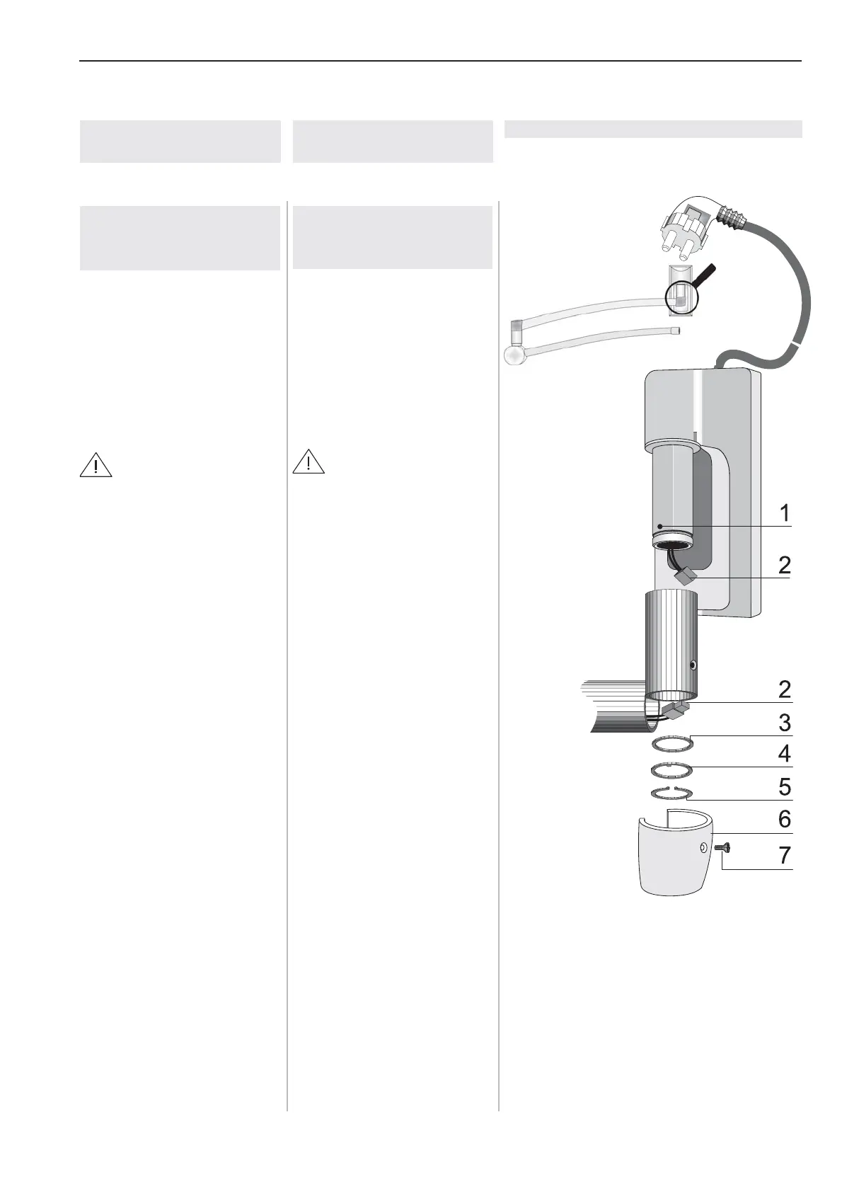
Abb. 2
1. Kreuzschlitzschraube (7) her-
ausschrauben und Abdeck-
kappe (6) nach vorne ziehen
und nach oben abnehmen.
2. Ausleger mit Federarm auf
den Zapfen des Wandlagers
einstecken.
VORSICHT-
Verletzungsgefahr:
Ohne montierte Scheibe (3) und
Nasenscheibe (4) wird der Siche-
rungsring (5) aufgedreht. Das Ge-
rät kann aus der Anbindung fallen
und zu Verletzungen führen.
Immer die Scheibe (3) und die
Nasenscheibe (4) montieren.
3. Scheibe (3) auflegen.
4. Nasenscheibe (4) in die Boh-
rung (1) einsetzen und den
Sicherungsring (5) montie-
ren.
5. Sicheren Sitz des Siche-
rungsringes (5) prüfen.
6. Elektrische Steckverbindung
(2) herstellen.
7. Abdeckkappe (6) aufsetzen
und mit der Kreuzschlitz-
schraube (7) verschrauben.
DeutschEnglish Abbildung / Figure
Figure / Abbildung 2
1 Hole
Bohrung
2 Electrical connection
Steckverbindung
3 Washer Ø 32.3 x 39 x 0.5 mm
Scheibe Ø 32,3 x 39 x 0,5 mm
4 Slotted cone
Nasenscheibe
5 Retaining Ring
Sicherungsring
6 Cover
Abdeckkappe
7 Cross-slotted screw
Kreuzschlitzschraube
3 Wall modell
3.2 Installing the extender
arm with spring arm
Fig. 2
1. Unscrew the cross-slotted
screw (7) and pull the cover
(6) forward and remove it up-
wards.
2. Place the extension arm with
the spring arm on the pin of
the wall bearing.
CAUTION -
Danger of injury
If the washer (3) and slotted cone
(4) is not installed, the retaining
ring (5) can get loosened. The
equipment can then fall out of its
mounting and cause injury.
Always install the washer (3) and
the slotted cone (4).
3. Install washer (3).
4. Insert the slotted cone (4) in
the hole (1) and install the re-
taining ring (5).
5. Check for firm seating of the
retaining ring (5).
6. Set up the electrical connec-
tion (2).
7. Put on the cover (6) and
screw it tight with the cross-
slotted screw (7).