INSTALLATION STEPS / INSTALLATION STEPS / ETAPES D'INSTALLATION / PASSAGGI
PER L'INSTALLAZIONE / PASSAGGI PER L'INSTALLAZIONE
1. Questo apparecchio è a prova d'acqua e d'umidità, ma non può essere immerso in acqua.
2. La posizione di montaggio di questo apparecchio dovrebbe poter reggere almeno 10
volte il peso della lampada.
3. Questo apparecchio è alimentato da corrente alternata ad alta tensione (HVAC).
Deve essere collegato al cavo di messa a terra e tenuto fuori da un facile accesso.
4. Questo apparecchio deve essere utilizzato in buone condizioni di dispersione del calore.
La temperatura durante l’utilizzo non dovrebbe superare i 45°C. Una temperatura di
utilizzo troppo elevata comprometterà gravemente l'apparecchio e ne influenzerà la durata.
Limitazioni dell’uso interno ed esterno
EN
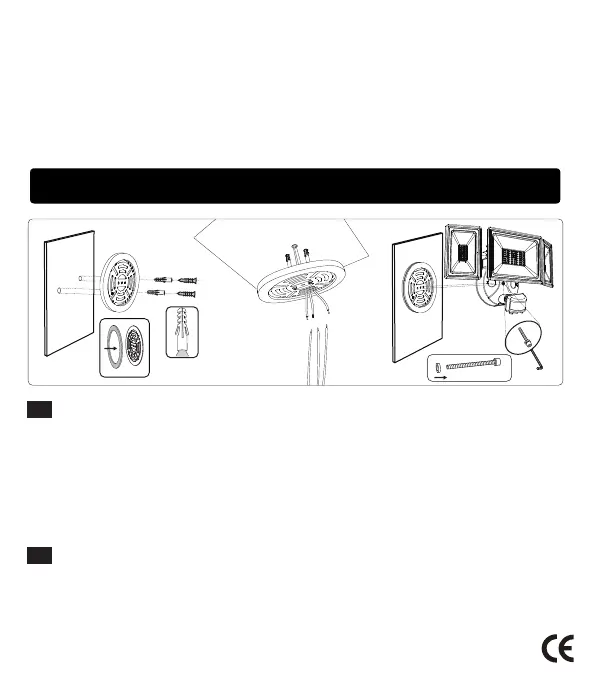
Step 1: Stick EVA cotton pad on the metal panel.
Drill two holes on the wall, fix the metal panel onto the wall with plastic expansion
nails and screws. Note: Please estimate and identify the distance and size of the holes
before drilling, and the metal panel has to be horizontally placed.
Step 2: Pass your power cord through the hole of metal panel. Then connect the Neutral line,
Live line and Ground wire of power cord with the corresponding wires.
Step 3: Thread the long screw into the silicone ring and insert it into socket hole.
Tighten it to the metal panel with an Allen key to make sure the lights is firmly fixed.
Note: 1. For wet location,make sure fill full the gap of EVA gasket and mouting
surface with sealing compund or silicon glue.
2. Mounting above 1.2m (4ft) of ground.
DE
Schritt 1: Setzen Sie die EVA-Baumwolle auf die Metallplatte.
Bohren Sie zwei Löcher in das Wand, und befestigen Sie die Metallplatte mit
KunststoffSpreiznägeln und Schrauben an der Wand. Hinweis: Bitte schätzen Sie den
Abstand und die Größe der Löcher vor dem Bohren ab, und die Metallplatte muss horizontal
platziert werden.
Schritt 2: Führen Sie Ihr Netzkabel durch das Loch der Metallplatte. Verbinden Sie dann
die Neutralleitung, die Stromleitung und das Erdungskabel in den entsprechenden
Kabelanschlü ssen. Hinweis: Wenn Ihre Kabelanschlüsse nicht direkt mit unseren
vorhandenen Anschlüssen verbunden werden können, kann das Kabel in unserem
Zubehör für den Anschluss verwendet werden.
 Loading...