727.447.6140 Page 2 onicon.com
ON
I
CON
Flow and Energy Measurement
FT-3500 Transmitter Quick Start Guide
ON
I
CON
Flow and Energy Measurement
FT-3500 Transmitter Quick Start Guide
727.447.6140 Page 3 onicon.com
NETWORK CONFIGURATION
Connecting via BACnet MS/TP Connecting via BACnet UDP/IP
1. Power on unit to verify is it functioning properly. Once
veried, power unit down.
1. Power on unit to verify is it functioning properly. Once
veried, power unit down.
2. Wire MS/TP cables to unit.
• The RS485 network cable connections are polarity
sensitive and must be connected the same way on
every device (i.e. + to + and - to -).
• Shield drain connections should be daisy chained in
the same manner as the signal cables for RS485. The
shield drain wire should be left unterminated at the
end of the cable and connected to shield only at the
network master controller. Shield wires must not be
connected to the RS485 connector on the FT-3500.
• The maximum number of devices allowed on an RS485
network segment without a repeater is 32. Adding more
than 32 devices to a single segment may reduce the
transceiver output voltage to a level that is too low to be
distinguished from background noise on the cable.
2. Connect ethernet cable to unit.
3. Connect power to unit. 3. Connect power to unit.
4. Navigate to the systems network conguration. From
the main menu select:
g User Congurations g Network g BACnet MS/TP
or MODBUS RTU
4. Navigate to the systems network conguration. From
the main menu select:
g User Congurations g Network g BACnet MS/TP
or MODBUS RTU
5. Congure device as needed. Default values are listed
below.
Baud Rates 38400
Device Address 17 (Default)
Device Instance 57017
Max Master 127
5. Congure device as needed. Default values are listed
below.
Default Address 192.168.1.24
Instance Number 57017
Subnet Mask 255.255.255.0
Gateway Address Programmable
UDP port (BACnet) 47808
TCP port (MODBUS only) 502
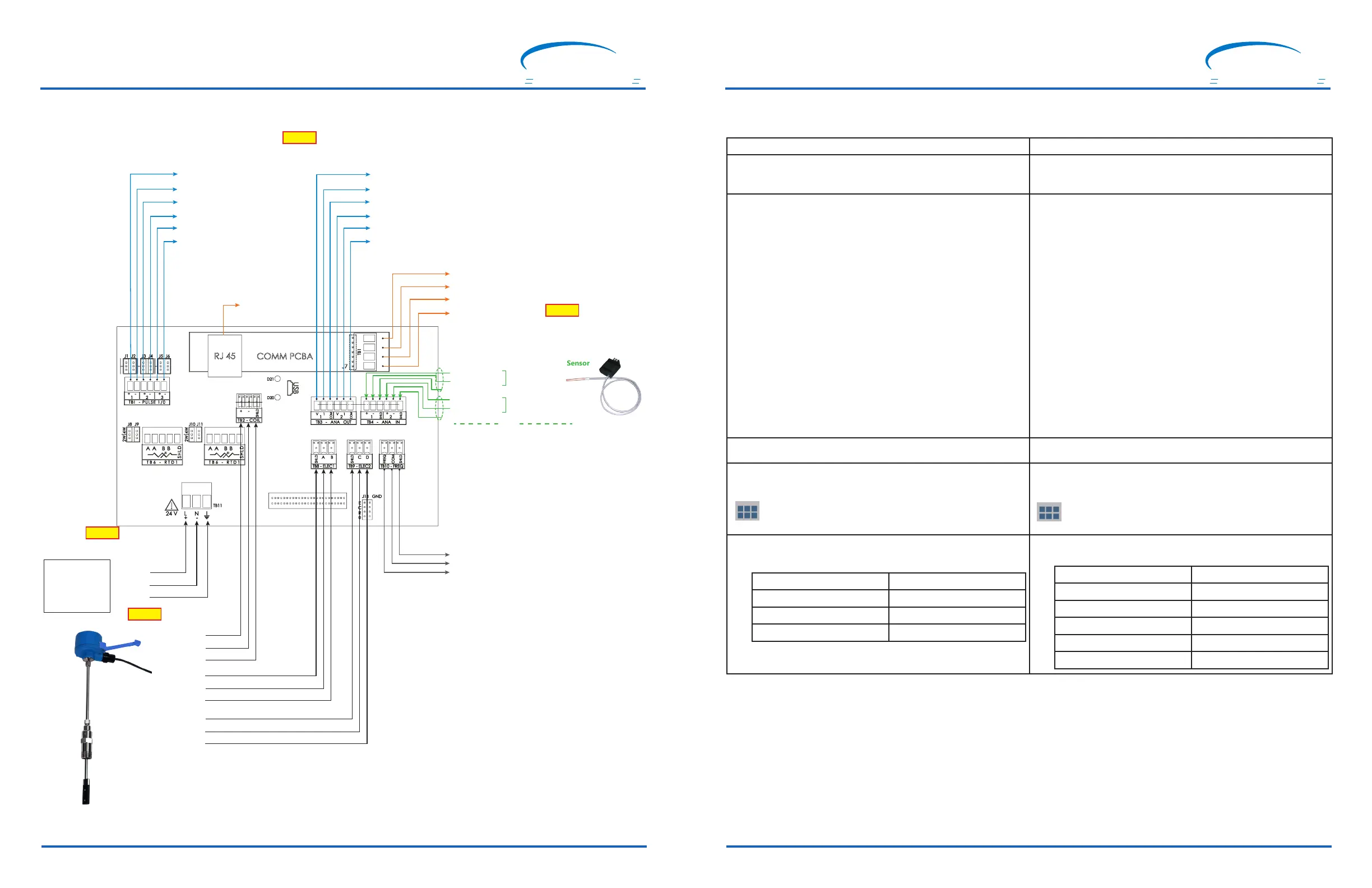
WIRING CONNECTIONS
24 V (+)
COMMON
GROUND
STEP 3
STEP 1
Remote Sensor Connections
PURPLE
BROWN
SHIELD
SHIELD
RED
BLACK
SHIELD
YELLOW
ORANGE
1
0
1
0
1
0
Required
22-26 VDC,
25 W Max
or
20-28 VAC,
30 vA Max, 60 Hz
SHIELD
(-) FREQUENCY
(+) FREQUENCY
Connection to an
ONICON Peripheral
(+) SIGNAL
(-) REFERENCE
(+) SIGNAL
(-) REFERENCE
Supply
Temperature
Return
Temperature
Confirm the temperature sensors are ONICON solid state
or non-ONICON RTDs
DO NOT USE
GND
(-)
(+)
BACnet MSTP or
MODBUS RTU
RJ45
BACnet IP or
MODBUS TCP/IP
(+) ANALOG OUT 1 (0-10V, 2-10V, 0-5V or 1-5V)
(+) ANALOG OUT 1 (4-20mA)
(-) COM
(+) ANALOG OUT 2 (0-10V, 2-10V, 0-5V or 1-5V)
(+) ANALOG OUT 2 (4-20mA)
(-) COM
Isolated Analog Out
(+)
(-)
(+)
(-)
(+)
(-)
Dry Contacts
Solid State ONICON Temperature Sensor
OR
TB6 RTD1 SUPPLY
TB7 RTD2 RETURN
A BROWN
A YELLOW
B WHITE
B GREEN
RTD (Non-ONICON) Temperature Sensor
VOLUME SCALED PULSE OUTPUT
DIRECTIONAL CONTACT FOR
FLOW ONLY VERSION
OR
ENERGY SCALED PULSE OUTPUT
MASTER ALARM CONTACT
STEP 2
Available Outputs
STEP 4
Only For (BTU) Energy Version
Input Power
(Class II Power Supply)

 Loading...


