Do you have a question about the Onkyo A-809 and is the answer not in the manual?
Critical components for fire/shock risk require replacement with specified parts.
Detailed performance metrics including power output, distortion, sensitivity, and frequency response.
Guidelines on fuse replacement, insulation resistance measurement, and voltage selector usage.
Instructions for workbench setup, including load, signal, and switch configurations.
Procedure for adjusting idling current using test points and semi-fixed resistors.
Steps to verify the operation of the protection relay and DC detection circuitry.
Detailed explanation of each pin's function for the TMP47C440AN microprocessor.
Further pin descriptions for the microprocessor, including input/output selectors and mode controls.
The main schematic diagram for the AC 120V model of the amplifier.
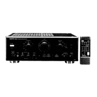
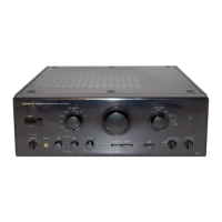
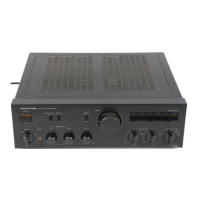
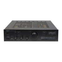
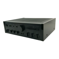
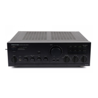
This document is a service manual for the Onkyo Integrated Stereo Amplifier, Model A-809.
The Onkyo A-809 is an integrated stereo amplifier designed to deliver high-quality audio output. It incorporates a microprocessor (TMP47C440AN) for control and management of various functions, including input selection, volume control, and protection circuitry. The amplifier features multiple input terminals for various audio sources such as Phono (MM/MC), CD, Tuner, Tape Play, and Aux. It also includes output terminals for tape recording and speaker connections. The unit is equipped with protection circuitry to safeguard against fire and electric shock, and it includes a relay system for speaker protection.
Power Output:
Dynamic Power:
Total Harmonic Distortion:
Intermodulation Distortion:
Damping Factor:
Input Sensitivity/Impedance:
Output Level/Impedance:
Phono Overload:
Tone Control (Vol -20 dB):
High Cut:
Frequency Response:
RIAA Deviation:
Subsonic Filter:
Signal to Noise Ratio (IHF-A):
Attenuator:
Muting:
Power Supply:
Dimensions (W x H x D):
Weight:
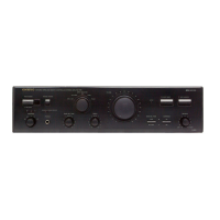
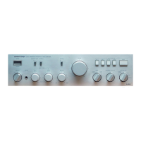
The amplifier supports a wide range of audio sources and offers comprehensive control over sound output. It includes tone controls for bass and treble, a high-cut filter, and a subsonic filter. The input selector allows users to switch between various audio components, while the volume control, attenuator, and muting functions provide precise control over audio levels. The presence of a voltage selector on worldwide models ensures compatibility with different local power supplies, requiring users to set the switch correctly before operation. Remote control initialization is also supported for convenience.
Safety-Related Components:
Replacing Fuses:
Insulation Resistance Measurement (U.S.A. model only):
Voltage Selector (Rear Panel):
Adjustment Procedures: