Do you have a question about the Onkyo A-8500 and is the answer not in the manual?
Detailed power ratings for various impedance and frequency conditions.
Specifies dynamic power output across different impedance loads.
Measures distortion levels at rated power and 1 watt output.
Quantifies intermodulation distortion at rated power.
Indicates the amplifier's ability to control speaker movement.
Lists input sensitivity and impedance for various input sources.
Specifies output levels and impedance for tape recording.
Details maximum input signal level for Phono (MM) before distortion.
Describes the range and effect of bass and treble controls.
Specifies the frequency and slope of the high-cut filter.
Outlines the frequency response for CD/Tuner and Phono inputs.
Shows deviation from the RIAA equalization curve for phono inputs.
Details the cutoff frequency and slope for subsonic filters.
Provides IHF-A weighted signal-to-noise ratios for different inputs.
Specifies the attenuation level for the muting function.
Lists power supply voltages and frequencies for different regions.
Provides the physical dimensions of the amplifier.
States the weight of the amplifier.
Instructions on replacing fuses with correct types to prevent fire hazards.
Procedure for measuring insulation resistance on US models.
Guidance on using the voltage selector for different power supplies.
Illustrates the signal path selection for various audio sources.
Depicts the tone control circuit and its relation to volume and balance.
Shows the power amplifier section, speaker output relays, and protection circuit.
Illustrates the regulated power supply stages and voltage distribution.
Shows main power and voltage selection connections for different regions.
Detailed schematics of the core audio processing and amplification circuits.
Schematic of the power supply unit including transformer and regulators.
Schematic of the protection circuitry for speaker and DC output.
Block diagrams for protective circuit IC (TA7317P) and O.P. Amp (NJM4560DX).
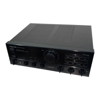
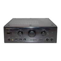
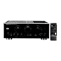
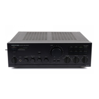
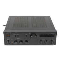
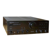
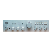
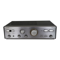
Identifies and describes the function of front panel controls and indicators.
Steps to prepare the unit and workbench before performing adjustments.
Procedure to adjust the idling current for optimal performance.
Steps to verify the correct operation of the protection relay and DC detection.
Testing the protection circuit's response to signal input and load conditions.
An exploded view illustrating the physical placement of major chassis components.
Lists part numbers and descriptions for front panel and chassis-related parts.
Lists part numbers for circuit boards, fuses, and connectors.
Detailed parts list for the main circuit board, including ICS, transistors, resistors, and diodes.
Parts list for the speaker switch circuit board.
Parts list for the input selector switch circuit board.
Parts list for the input LED board.
Parts list for the equalizer circuit board.
Parts list for the power supply circuit board.
Lists items included in the product packaging.
Diagram illustrating how to connect various audio components and speakers.
Shows power cord connection and notes on speaker impedance for different regions.