Do you have a question about the Onkyo A-8800 and is the answer not in the manual?
Replace fuses with the same type and rating for continued protection.
Measure insulation resistance (>10 MΩ at 500V) on US models.
Ensure voltage selector matches local power supply before use.
Prepare the unit by placing it correctly and setting switches.
Adjust R531/R532 for 15mV±5mV at test point VCT-IID.
Test relay and DC detection circuitry operation upon power on/off.
Adjust resistors R815, R813, R811 to minimize distortion elements.
Parts list for the Input Switch & Equalizer circuit board.
Parts list for the Mode Switch circuit board.
Parts list for the Tone Control circuit board.
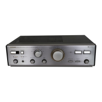
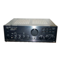
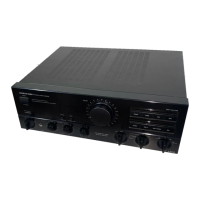
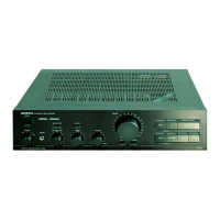
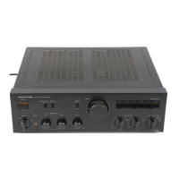
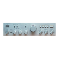
The Onkyo A-8800 is an integrated stereo amplifier designed to deliver high-quality audio performance across a variety of input sources. This device serves as the central hub for an audio system, allowing users to connect and manage multiple audio and video components, process digital and analog signals, and amplify sound for speaker output. Its integrated design aims to simplify the setup of a home audio system while offering comprehensive control over sound reproduction.
At its core, the A-8800 functions as a powerful amplifier, capable of driving speakers with substantial output. It incorporates both analog and digital input capabilities, making it versatile for modern audio setups. The amplifier features a D/A converter section, enabling it to process digital audio signals directly from sources like CD players, DAT recorders, and other digital audio units. This eliminates the need for an external D/A converter, streamlining the signal path and potentially improving audio fidelity.
The analog input section includes a dedicated phono stage with selectable MC (Moving Coil) and MM (Moving Magnet) cartridge inputs, catering to vinyl enthusiasts with different turntable setups. Other analog inputs are provided for CD, Tuner, Tape, VCR, and VDP (Video Disc Player), allowing for a wide range of legacy and contemporary analog sources. A "Processor In" and "Pre Out" connection are also available, offering flexibility for integrating external audio processors or connecting to a separate power amplifier.
For digital audio, the A-8800 provides coaxial and optical inputs, supporting various digital audio formats and sampling frequencies. The D/A converter processes these signals before they are fed into the amplifier's analog stages.
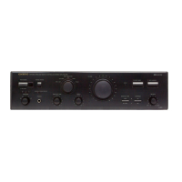
The amplifier includes comprehensive tone controls, featuring Bass, Treble, and a unique Contrabass adjustment, allowing users to tailor the sound to their preferences and listening environment. A "Source Direct" switch bypasses these tone controls for the purest possible signal path, ideal for audiophiles who prefer an uncolored sound. The "Mode" selector allows switching between stereo and mono playback, while a "Muting" function provides quick volume reduction.
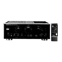
A "Video Mode" switch is also present, indicating the amplifier's capability to integrate with video sources, likely for managing audio from VCRs, VDPs, and CDVs (Compact Disc Video). This suggests a focus on home entertainment systems where both audio and video components are present.
The A-8800 incorporates a protection circuitry designed to safeguard the amplifier and connected speakers from damage due to various faults, such as excessive DC voltage or short circuits. This system includes a relay that disengages the speaker output when a fault is detected, ensuring reliability and longevity.
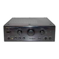
Operating the A-8800 is designed to be intuitive, with clearly labeled controls on the front panel. The "Input Selector" buttons allow users to easily switch between connected audio sources, with corresponding indicators to show the active input. The "Volume" control adjusts the overall output level, while the "Balance" control allows for left/right channel adjustment.
The "Cartridge Selector" switch (MC/MM) is crucial for turntable users, ensuring proper impedance matching for their phono cartridge. The "Rec Selector" switch provides flexibility for recording from one source to another, a common feature in integrated amplifiers for tape decks or other recording devices.
The "Speaker Selector" switch allows users to choose between two sets of speakers (A or B), or both (A+B), or to turn the speakers off entirely, which is useful when using headphones. A headphone jack is conveniently located on the front panel for private listening.
The digital lock indicator provides visual feedback on the status of the digital input signal, confirming that the D/A converter has successfully locked onto the incoming digital stream.
The rear panel offers a comprehensive array of connections, including RCA jacks for analog inputs and outputs, coaxial and optical ports for digital inputs, and robust speaker terminals. A voltage selector is present on worldwide models, allowing the unit to be adapted to different local power supplies, a critical feature for international use. This selector must be set correctly before powering on the device to prevent damage.
Maintenance of the A-8800 primarily involves ensuring proper operation and addressing potential issues as outlined in the service manual. A key maintenance feature is the clear guidance on replacing fuses. The manual explicitly states that for continued protection against fire risk, fuses must be replaced with the same type and rating. This is a fundamental safety and operational requirement.
For U.S.A. models, an insulation resistance measurement is recommended to ensure that exposed parts are acceptably insulated from the supply circuit. This is a critical safety check to be performed before returning the appliance to the customer after service.
The service manual also details adjustment procedures, such as idling current adjustment and checking the protection circuitry. These procedures are typically performed by qualified service technicians to ensure the amplifier operates within its specified parameters and that safety features are functioning correctly. The idling current adjustment, for instance, involves setting specific voltage levels on the circuit board, which is vital for the amplifier's stability and performance.
The protection circuitry check involves verifying that the relay turns on and off as expected and that the DC detection and servo circuitry operate correctly, disengaging the speakers if an unsafe DC voltage is present at the output. This ensures that the amplifier protects itself and connected speakers from potentially damaging conditions.
The DAC block adjustment section provides instructions for confirming the display of sampling frequencies and for adjusting distortion elements. These adjustments, involving semi-fixed resistors, are crucial for optimizing the performance of the D/A converter and minimizing audio distortion, ensuring the highest possible sound quality from digital sources. These are specialized adjustments that would typically be performed by a technician with appropriate test equipment, such as a distortion meter and an oscilloscope.
The modular design, implied by the detailed parts lists for various circuit boards (e.g., Input Switch & Equalizer, Mode Switch, Tone Control, Power Amplifier, Digital Circuit, Digital Power Supply), suggests that components can be serviced or replaced individually, facilitating repair and extending the life of the unit. The identification of "safety-related components" by a specific mark (A) on schematic diagrams and parts lists is a crucial maintenance feature, guiding technicians to use only specified Onkyo parts for these critical components to maintain safety standards and prevent fire or electric shock risks.
| Dimensions | 435 x 144 x 391mm |
|---|---|
| Weight | 11.2kg |
| Damping factor | 100 |
| Speaker load impedance | 4 - 16 ohms |
| Input Impedance | 47k ohms |