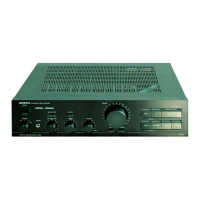
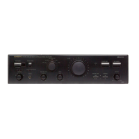
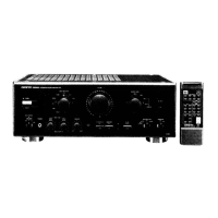
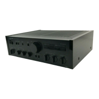
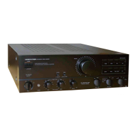
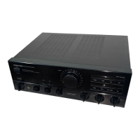
EasyManua.ls Logo

Onkyo A-8150 Service Manual

Onkyo A-8150
10 pages
To Next Page IconTo Next Page
Page #1 background imageLoading...
Page #1 background image
ONKYO
A-8150
SERIAL
NO.
3268
SERVICE MANUAL
Integrated Stereo Amplifier
MODEL A-81S0
UD
120V AC, 60Hz
UG
220V AC, 50Hz
UQ
240V AC. 50Hz
UW
120V/220V AC, SO/60Hz
SAFETY -RELATED COMPONENT WARNING!!
COMPONENTS IDENTIFIED BY MARK
!;)..
ON THE
SCHEMATIC DIAGRAM AND IN THE PARTS LIST ARE
CRITICAL FOR RISK OF FIRE AND ELECTRIC SHOCK.
REPLACE THESE COMPONENTS WITH ONKYO PARTS
WHOSE PARTS NUMBERS APPEAR AS SHOWN IN THIS
MANUAL.
MAKE LEAKAGE-CURRENT OR RESISTANCE MEA-
SUREMENTS TO DETERMINE THAT EXPOSED PARTS
ARE ACCEPT ABLY INSULATED FROM THE SUPPLY
CIRCUIT BEFORE RETURNING THE APPLIANCE TO
THE CUSTOMER.
TABLE OF CONTENTS
Item
Page
Specifica tions
2
Precautions
2
Block diagram
3
Adjustment procedures
4
Front panel facilities
4
Chassis exploded view
5
Exploded view parts list
6
System connections
6
Printed circuit board parts list
7
Schematic diagram
9, 13
Packing procedures
11
Printed circuit board view
12
iONKYO·
AUDIO COMPONENTS
-1-
Question and Answer IconNeed help?

Do you have a question about the Onkyo A-8150 and is the answer not in the manual?

Onkyo A-8150 Specifications

General IconGeneral
BrandOnkyo
ModelA-8150
CategoryAmplifier
LanguageEnglish

Summary

SAFETY-RELATED COMPONENT WARNING!!

SPECIFICATIONS

PRECAUTIONS

Replacing the fuses

Instructions for replacing fuses to maintain safety and prevent fire risk.

Insulation resistance measurement

Procedure for measuring insulation resistance on U.S.A. models for safety.

Voltage selector (rear panel)

Guide on using the rear panel voltage selector for different power supplies.

BLOCK DIAGRAM

SCHEMATIC DIAGRAM

ADJUSTMENT PROCEDURES

FRONT PANEL FACILITIES

Input selector switches and indicators

Controls for selecting audio input sources (CD, Phono, Tuner, AUX, Tape).

CHASSIS-EXPLODED VIEW PARTS LIST

Related product manuals